Creating locations
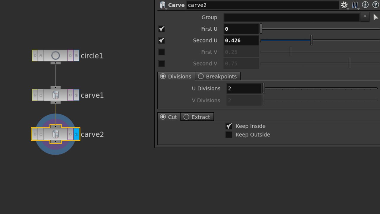
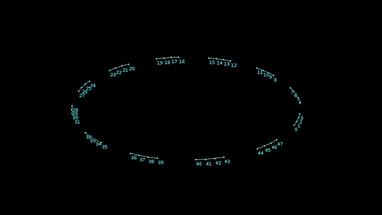
Before creating any visible objects, we need locations. At the scene level (/obj), create a circle and double click into it (make sure it’s a bezier curve primitive with 12 divisions and sitting on the ZX plane). It’s best to view point numbers at this stage as the first few changes aren’t visually identifiable. We need to translate each of these divisions into its own primitive to coincide with the months of our data. To do this we’ll need two carve SOPs. One to first cut our circle at each division (breakpoints), and a second to let us scale the size of each segment (divisions). Create two carve SOPs and connect them from our circle.


Node parameters for carve


Play with the second U/end location parameter of the second carve SOP and notice how it defines the segment size. Remember to click the blue display flag of the node you’re working with to see visible changes in the scene view. Also, keep the geometry spreadsheet pane visible nearby and toggle between viewing points and primitives. Notice how carve is creating primitives from the original circle. Because we might want either a straight edged dodecagon or a circle, add a resample SOP at the end of our chain and enable “maximum segments” rather than “maximum segment length”. Resample lets us re-define the number of points in each segment, so a value of 1 will give us two points and one segment (and a straight edge), while a higher number will generate more points, smoother geometry and a more circular form. Feel free to change this at any time (later we’ll make a more accessible control panel).