Add Labels and Rings
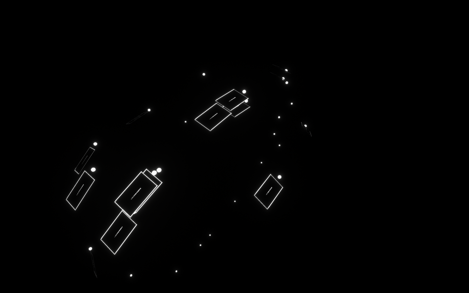
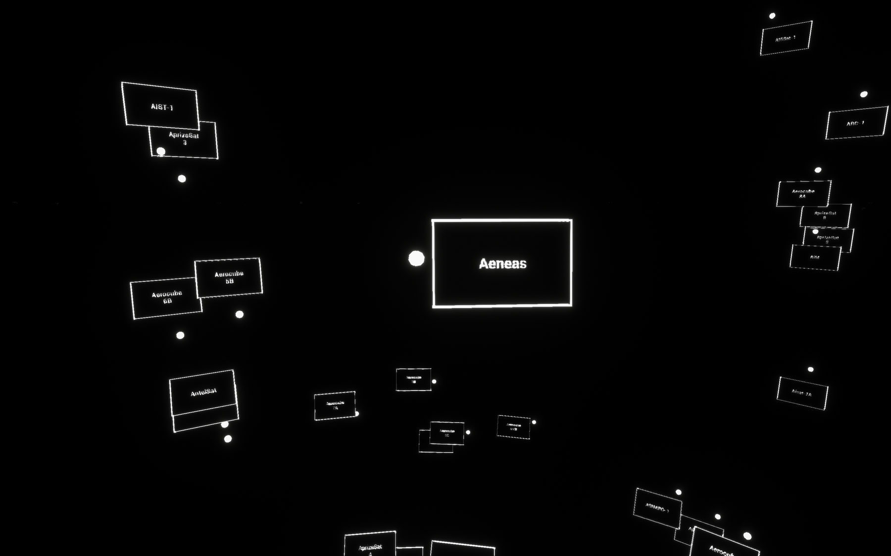
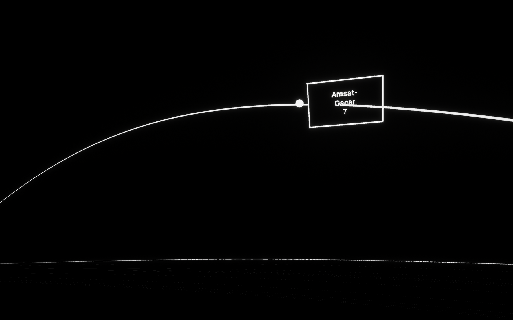
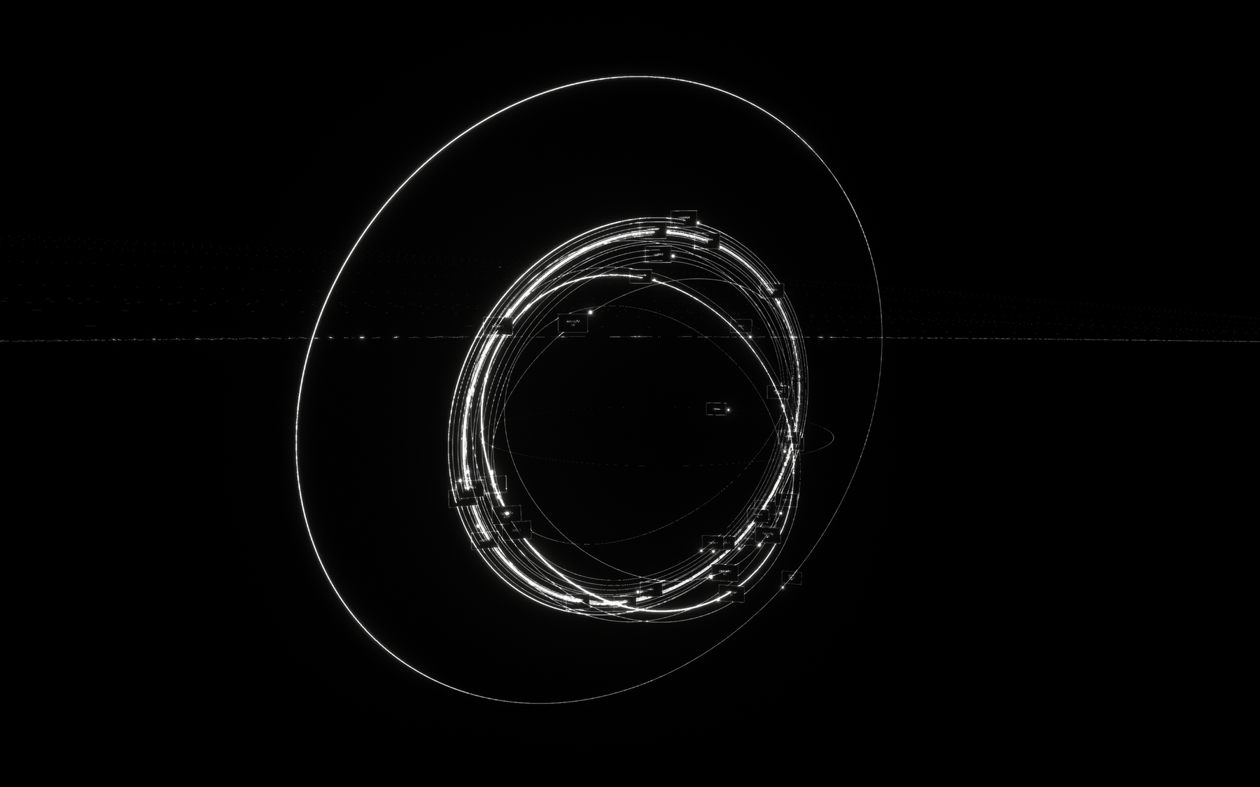
Let's continue with our Satellite class to add labels and rings to each object. We could theoretically add as much information as we want to our labels, but for this tutorial we'll just aim to display the "Official Name of Satellite" property. For our rings, these are slightly tricky but will come together quickly. Here's where we'll aim to be by the end of this page.
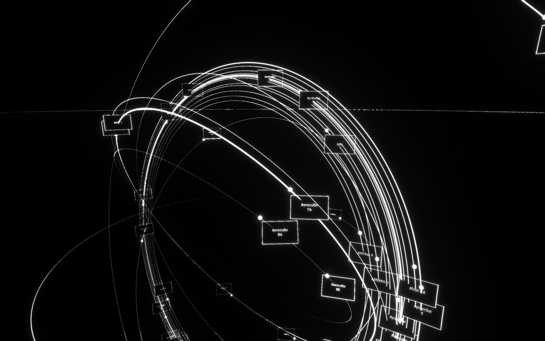

🏷 Create labels
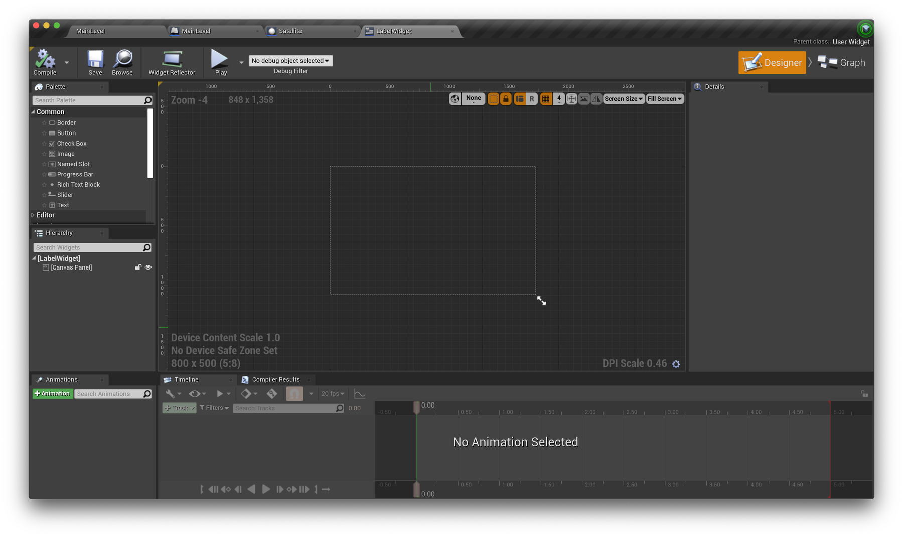
To add labels to our objects in 3D space, we'll first create a Widget. You can read more about widgets here. They're traditionally used for UI elements: menus, HUDs, stats etc. As we want to attach labels to our satellite objects, after creating our widget, we can add a widget component to our Satellite actor to draw these labels in 3D space. Let's get started.
Create a new Widget
In your Satellite folder (Content Browser), select Add New → User Interface → Widget Blueprint and name it LabelWidget. Open this asset and take a look around the Designer interface. Resize your widget canvas by dragging the white arrows and aim for a rough size of 800x500px. This exact size isn't too important as we're not drawing to our viewport.

Set DPI Scaling to 1
In short, the DPI Scaling option allows for interface elements (text, buttons, icons, menus etc) to scale to different sizes depending on the resolution of the screen they're being viewed on. This allows for graphics to appear the same "real world" size between a 2K screen and a 4K screen, for example—where the 4K screen is in fact drawing 2x the amount of pixels per inch.
For our project, the default settings can make the next steps involving sizing elements somewhat confusing, so lets adjust the DPI Scaling settings of your project to a consistent value of 1 in Project Settings → User Interface → DPI Scaling. To do this, find the DPI Scaling graph, and select the existing points and press delete to remove them. Then, shift + left click to add a new point, set it's Resolution to 0.0, and Scale to 1.0.
Read more about DPI Scaling here.
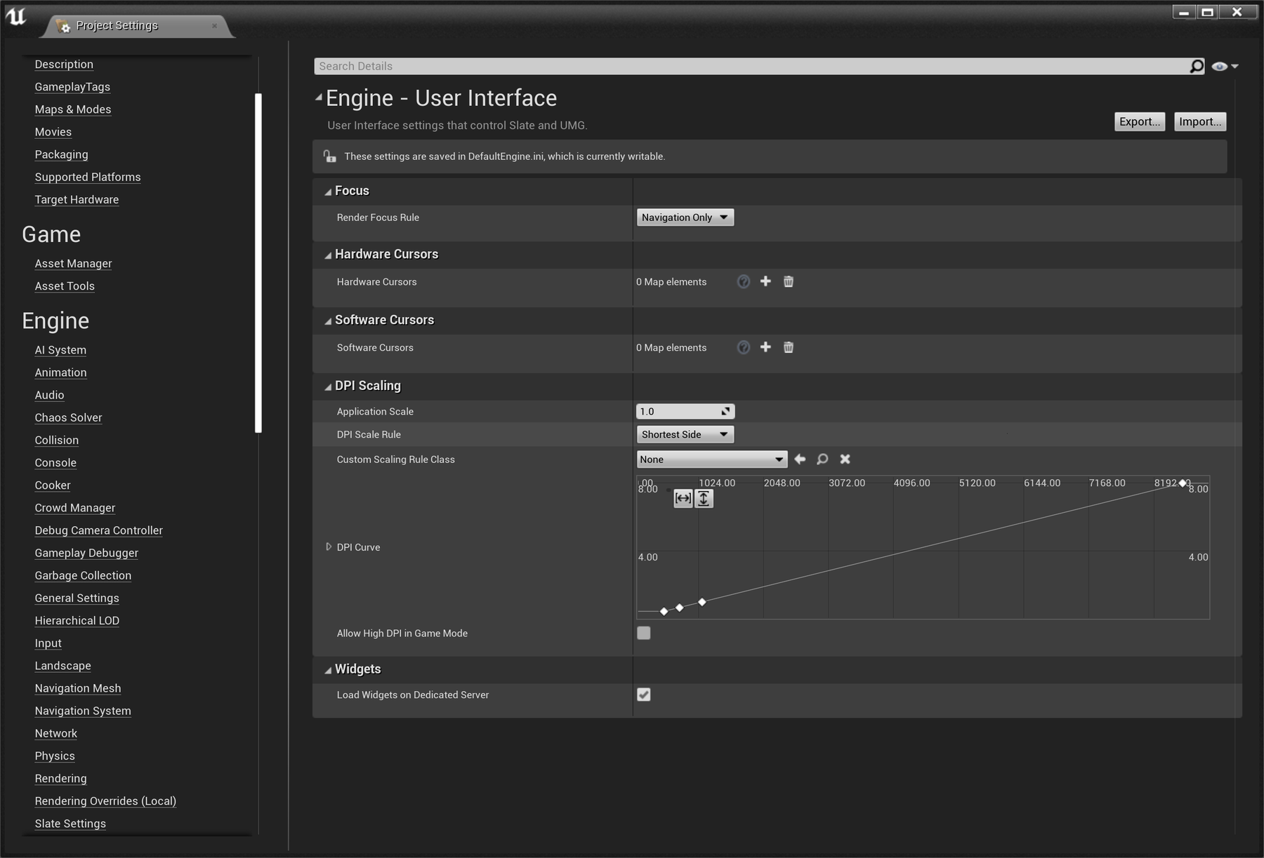

Before — UE4's default DPI scaling settings.
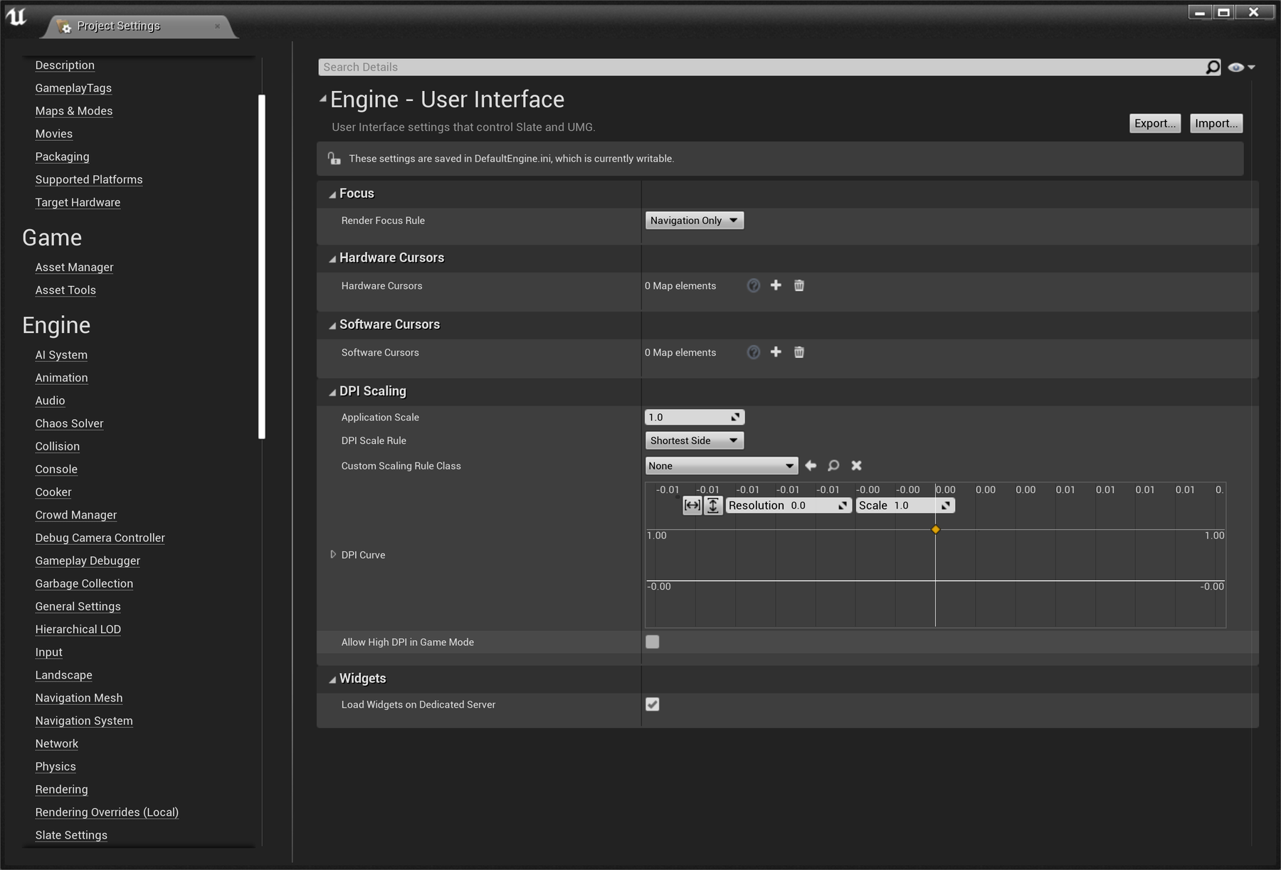

After — consistent scaling of x1 across all resolutions.
The video below will demonstrate the next steps. In short, we will:
-
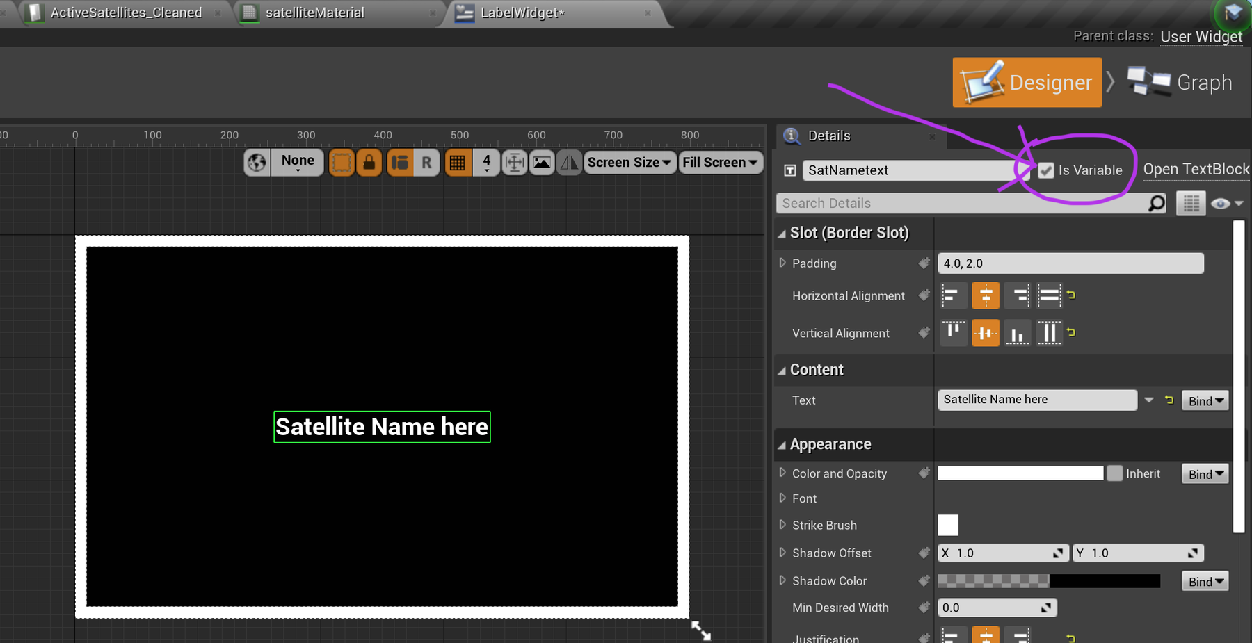
Create black background with a white outline by adding one full-sized Border layer painted white, and another slightly smaller Border layer painted black.
-
Add a Text layer in the centre of the canvas.
- Click on the text layer object to show its Details Parameters on the RHS. Locate the "Variable" toggle (see pink arrow in diagram). Turn it ON to promote SatNametext to a variable.
Being made a Variable means we can find it later in a Blueprint (to set the name).

Add a widget component to your Satellite
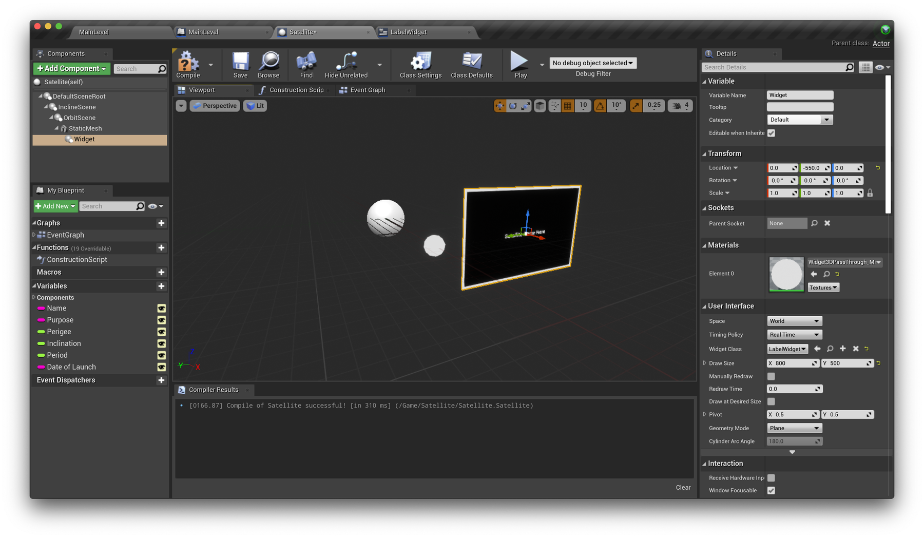
With our LabelWidget created, we're ready to add it to our Satellite class as another component. Head back to your Satellite class and Add Component → Widget and attach it to your StaticMesh component. In the Details panel on the right, set the Widget Class option to your newly created LabelWidget, and set the Draw Size to 800 x 500. Also, scroll down to Collision and set Collision Presets to NoCollision.
You should now see your widget floating in 3D space, attached to your sphere! We've adjusted the Y position of the widget to appear off to the right of the sphere.

Run and test
Before you hit play, drawing widget components on 1400+ objects can be quite expensive. Let's reduce the number of objects while we're developing our labels. K.I.S.S.
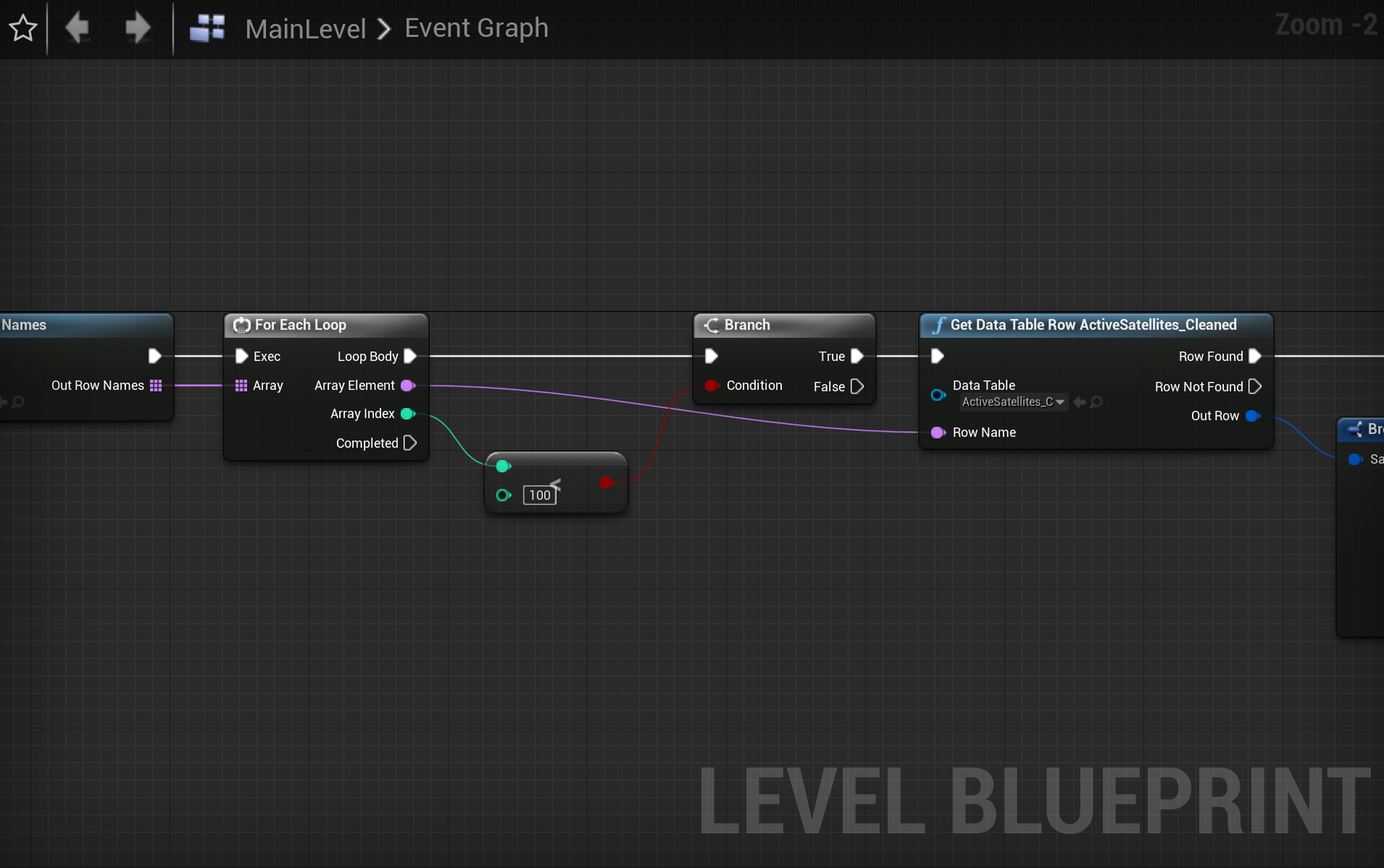
Head back to the Level Blueprint where we read the Data Table and create new Satellite objects. Locate the For Each Loop Node. LMB Click-and-hold on its output "Loop Body", then drag out a white line. This will let you add a new node. Make it a Branch node. Type "BRA" to narrow the search. Sometimes the Branch Node will be already inserted into the flow of nodes. Other times, depending on how the node was added, you have to wire up the white lines for exec.
Next we'll add another node which connects to the Condition input on this new Branch Node.
The idea is to check the current Array Index value is less than some limit with an integer < integer node. If true, let's proceed. This will cap the number of objects being spawned, to say 100. Experiment with this number and see what your system is happy to work with.
Make sure the "exec" white lines are all connected, from the first Event Begin Play node through to the last nodeSpawnActor Satellite. Notice the Branch Node needs exec lines on it's input and output.
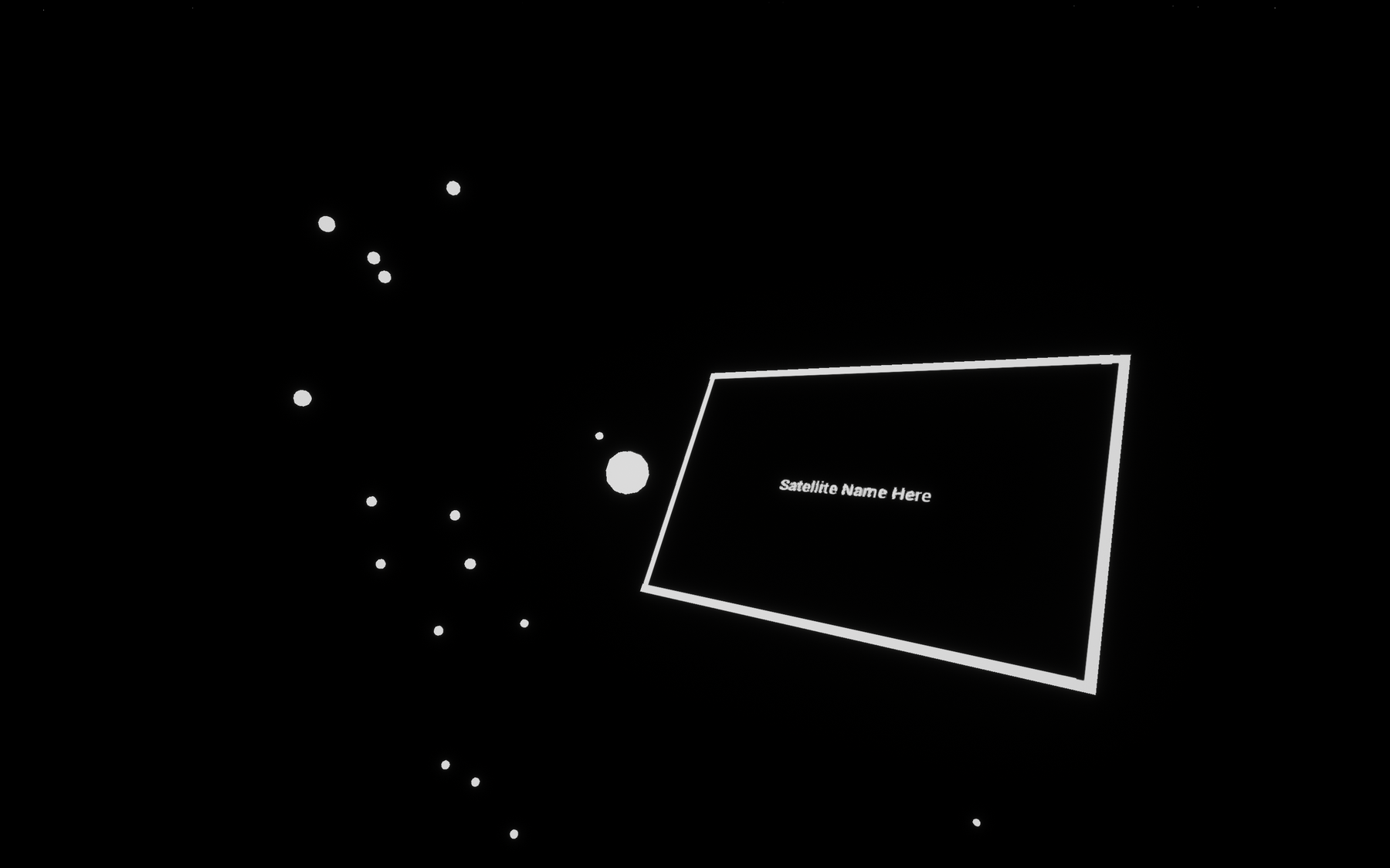
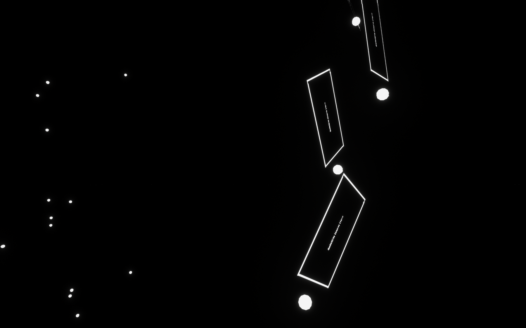
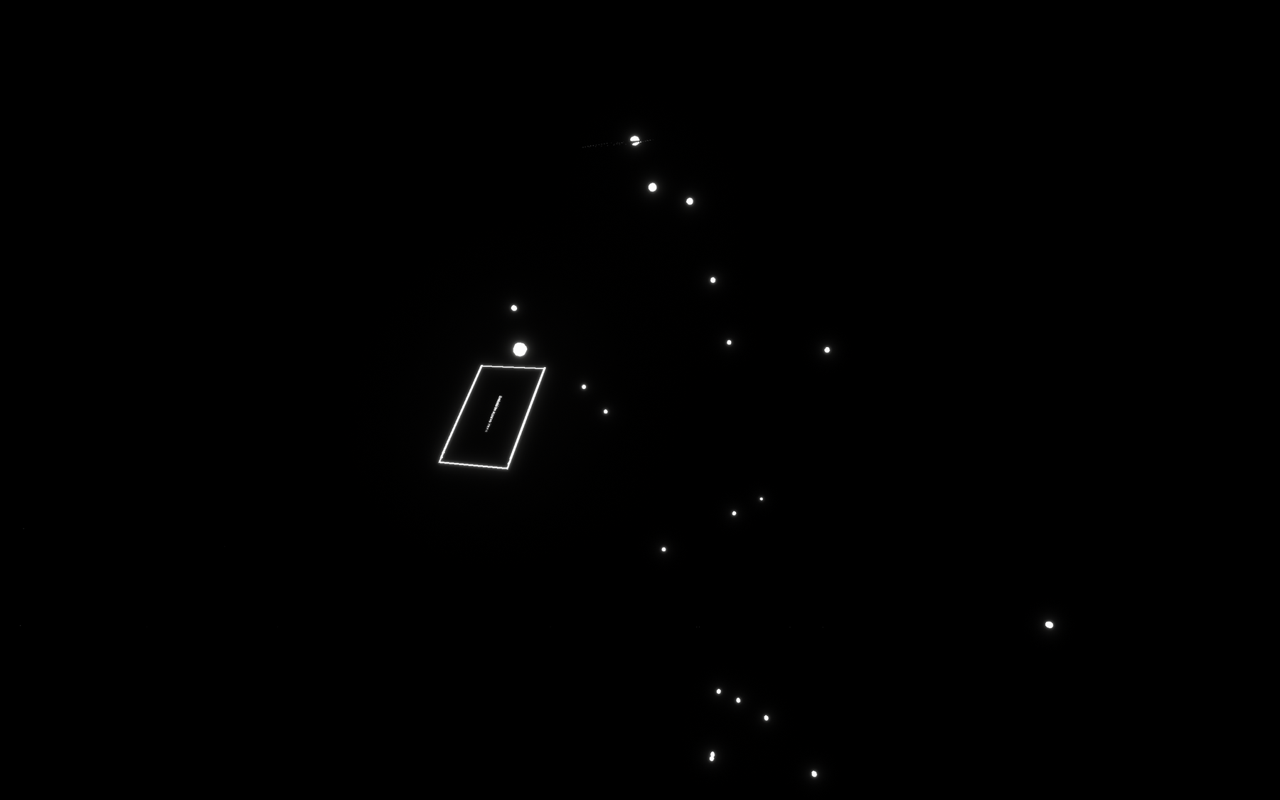
You should now hopefully see some oddly positioned labels next to your spheres! Clearly we have some work to do yet, but this is a great start.





Rotate labels to face the camera
Let's make sure these labels are always rotated to face the camera. Before we do this, add a new variable to your Satellite class called Show Details and set it to type boolean. Compile your blueprint and set the default value to true (ticked). We're going to use this to easily toggle the visibility of our labels and future rings.
Head back to your Satellite Event Graph. Note there's a couple of blueprint graphs now, such as the MainLevel Event Graph. You want the Satellite Event Graph . We will continue working from the end of the chain at the AddRelativeRotation node ...
But first - a function!
Let's create our first function to keep organised. Next to Functions (left), press + to create a new function, named FaceLabelToCamera. In this function, start with a simple Branch node and connect a reference to Get Show Details to the Condition input. See below.
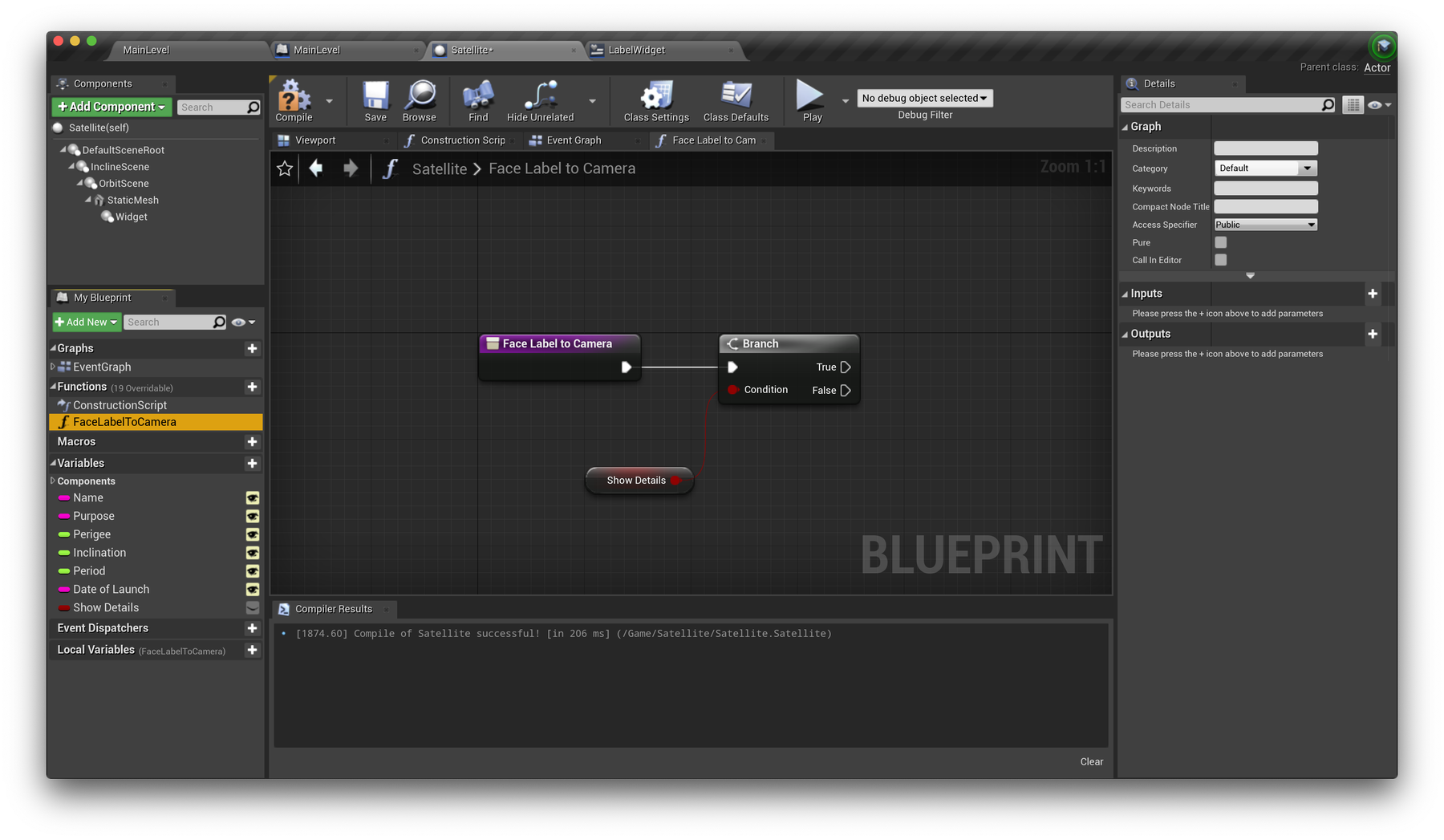

Then, back in your main Event Graph, drag and drop this function and add it to your chain. Now we can keep all the logic for rotating our labels inside the function without cluttering our main Event Graph.
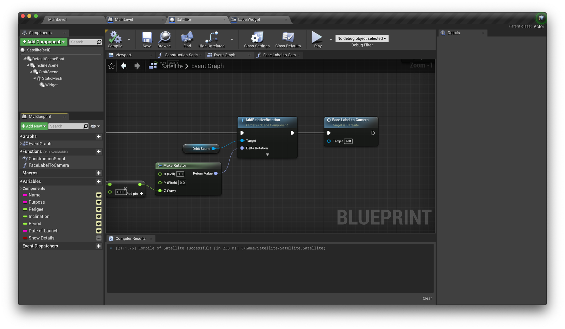

Back to your function, let's continue from the True pin of the Branch. To have our Widget component rotated to constantly face the camera, we'll make use of some very helpful nodes that take care of the hard work. Drag in references to your Widget and StaticMesh components. Your widget might be called "LabelWidget". Drag them from the list on the LHS into the blueprint. Nodes for them appear. In the next picture (below) the LabelWidget is just called Widget.
From the LabelWidget output connector, LMB on it and drag out a wire. In the menu which appears select to add a SetWorldRotation node. Type SETWO to narrow the search for the node.
The next couple of nodes are easier to add if you take a look at the picture below. They're going to connect into the Rotation input of the SetWorldRotation node you just added. Let's start from the Static Mesh node you dragged-in. Move it to the bottom-left of your blueprint, in anticipation the next couple of nodes will eventually link-up with the SetWorldRotation node on the rightside of the Blueprint. Like the picture below.
The rotation value required for each label will come from a Find Look At Rotation node. It will compare the locations of our Static Mesh and the game camera.
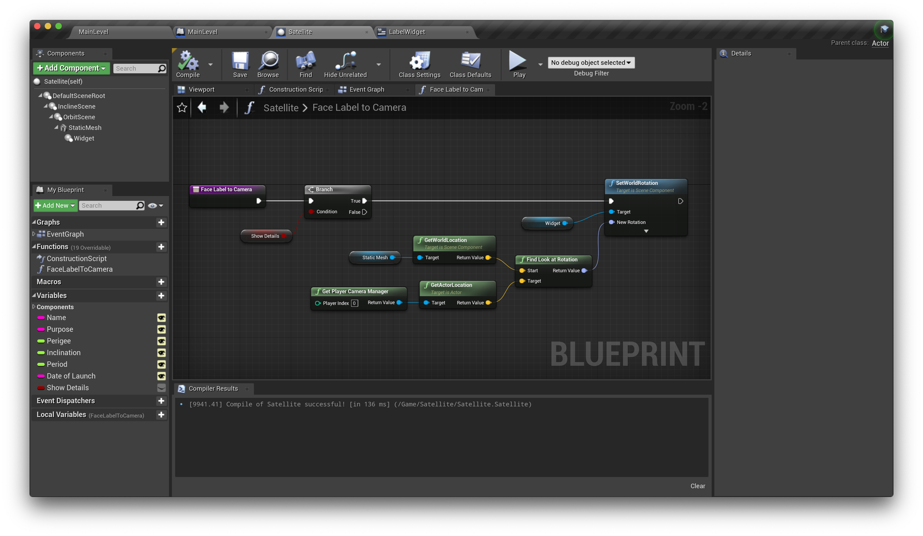

Great! Now if Show Details is set to true, these calculations will occur and our labels will always face the camera. Later, we will toggle the visibility of our labels based on multi-user cursors which will simply need to toggle this boolean.
Display each satellite's name
Our labels are looking good, but "Satellite Name Here" isn't ideal. Let's fix that. In your Satellite class, head to the end of the chain from your Event BeginPlay node. This should finish with setting the location of your StaticMesh component.
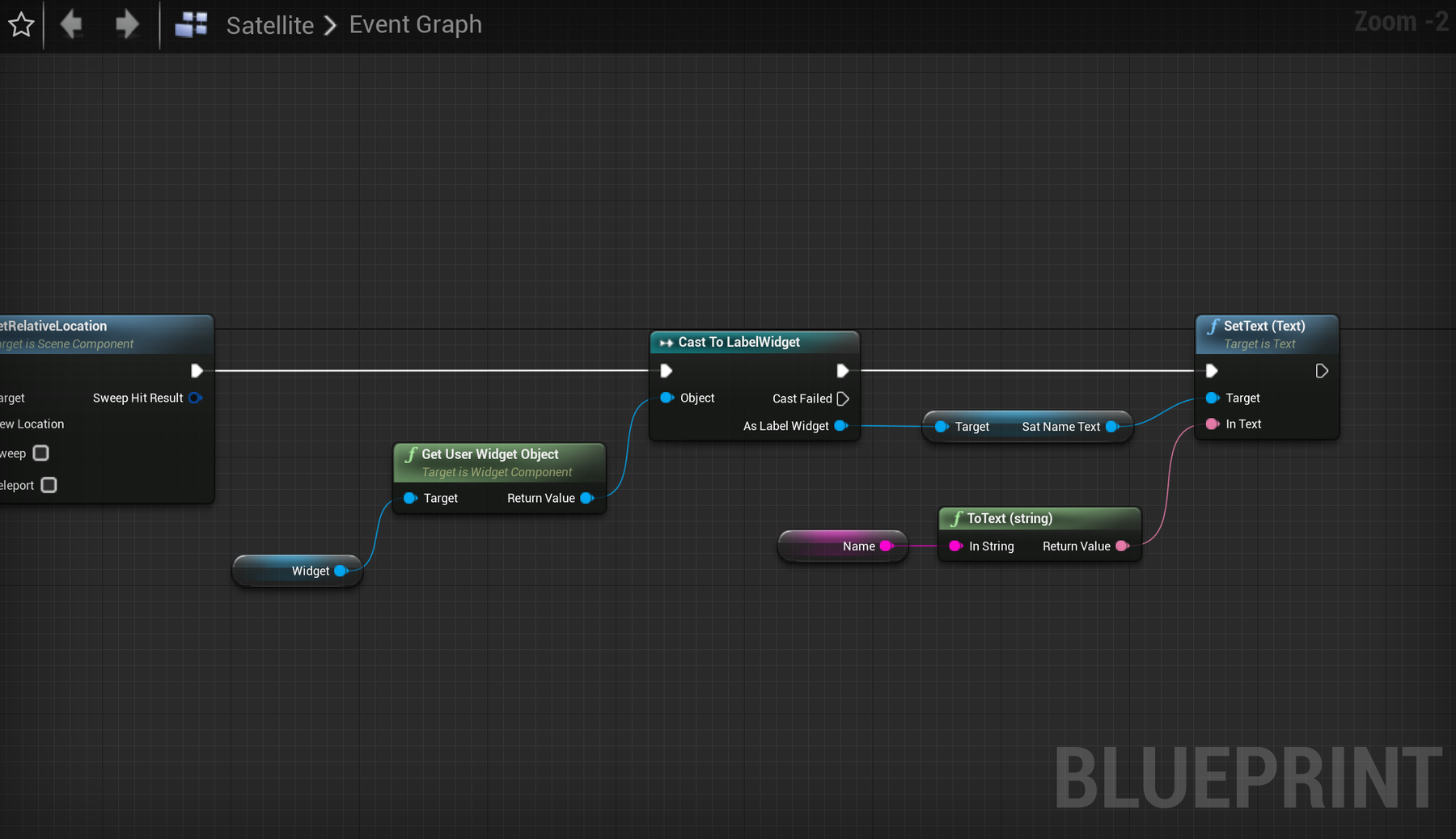
Drag in a reference to your Widget component. From this, add a Get User Widget Object node to retreive the widget "object" and pass the Return Value of this into a Cast To Label Widget node. In short, these are necessary steps to convert our component into a LabelWidget type object for UE to interact with.
From the As Label Widget output, search for Get SatNameText to retreive that text layer. Place the node. If it is not there, go back to your Widgets Panel and check that you enabled the "Is Variable" toggle for the "set name here" SatTextname widget. If it's not exported as a variable, then it won't show up in the Node Action Menu.
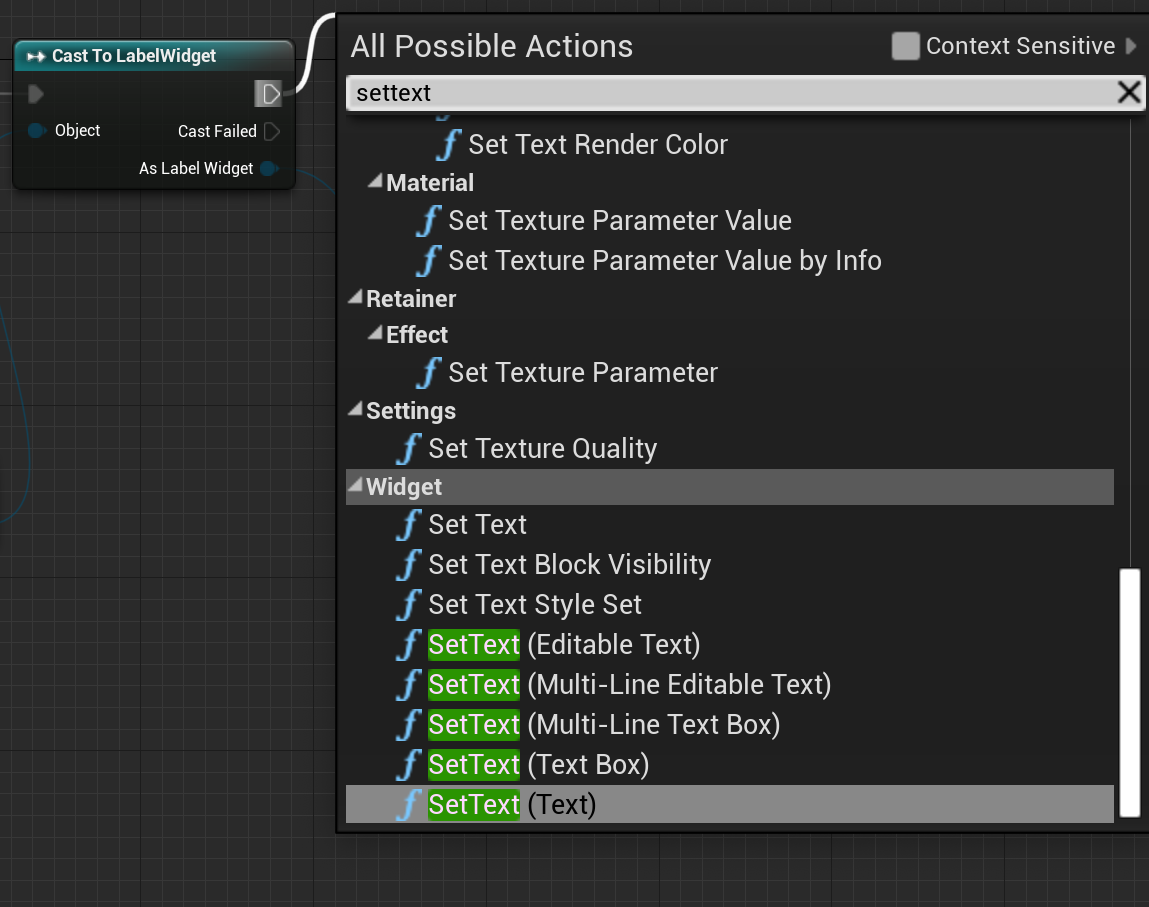
The next node is a SetText node.
When you drag out the wire from the output of the Cast to LabelWidget the node menu comes up.
enter these letters in the pop-up menu: s e t t e x t
You'll see the following SetText Nodes (right). Each takes a different Target. You want to choose the one which says "(Text)".

We are going to set the text on each Satellite's Label Widget. Let's make it the Satellite Name.
Drag in a reference to the Name variable from the List of Variables. You'll find this Name with a pink dot beside it in the panel to the left of the Blueprints panel. Drag that "Name" into the Blueprints area. It will become a pink coloured node. Wire its output to the In Text input connector on the SetText Node. Automagically a toText(string) conversion node is inserted. Thanks UE4 Editor!
Here's what your blueprint should be looking like now.


⭕️ Create rings
At the moment, our satellites look to be floating in 3D space, and it's hard to understand their paths of orbit, especially at slow speeds or in still screenshots. Let's work on drawing some rings to help visualise these paths. The way we'll achieve this is to create a material that draws a ring onto a flat plane. The material will be masked so we only see the ring while the remaining square plane geometry is hidden.
We're going to be following the steps of this very helpful tutorial by Rohit Kotiveeti to create a circle material. Have a watch first as well move through the material setup quickly.
Create the ring material
In your Satellite folder, create a new material named OrbitRing.
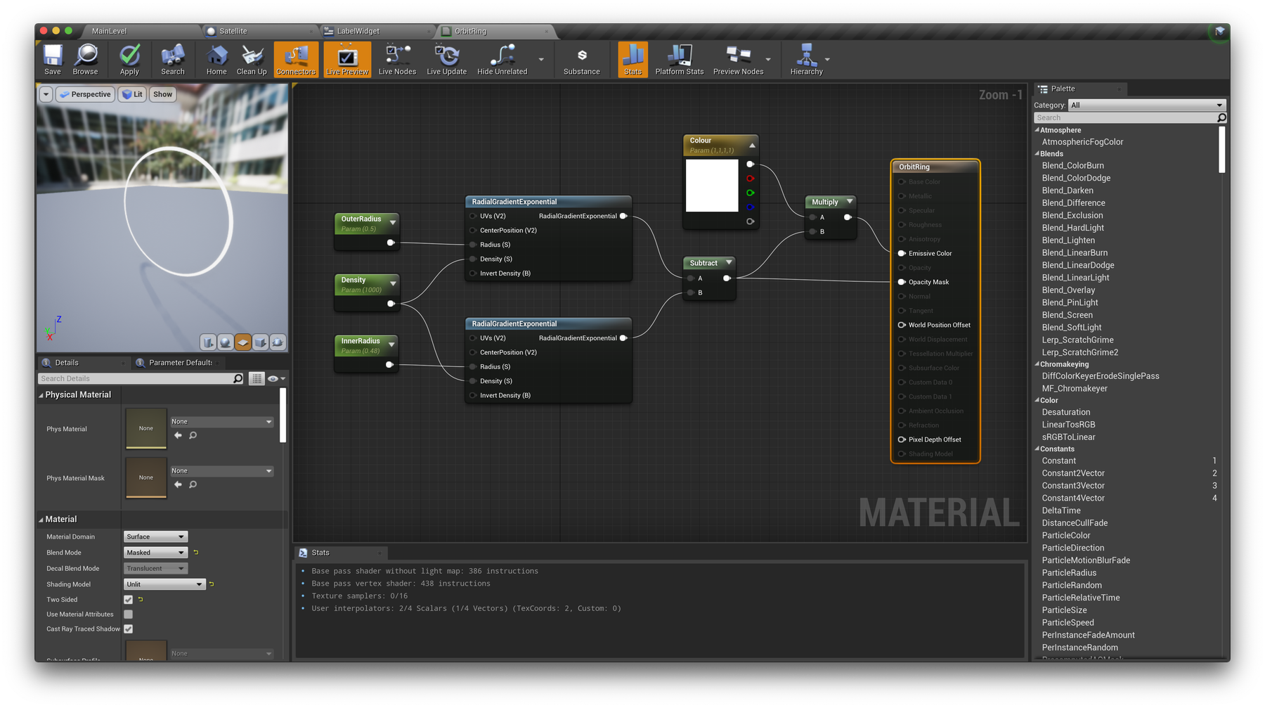
- Set the Blend Mode from Opaque to Masked. Set the Shading Model to Unlit. Enable Two Sided.
- Add two ScalarParameter nodes named OuterRadius and InnerRadius. Pass each into the Radius input of two RadialGradientExponential nodes.
- Set the OuterRadius value to
0.5and the InnerRadius value to0.4. We will adjust the InnerRadius value to control the ring thickness per satellite. - Create a single ScalarParameter node titled Density with value
1000and wire this to the Density input of both RadialGradientExponential nodes. - Subtract the output of the second RadialGradientExponential node (B) from the first (A).
- Add a Constant3Vector. Right-click → Convert to Parameter and name it Colour. Multiply this with the result from Subtract and connect to Emissive Color.
- Add another connection from Subtract to Opacity Mask.
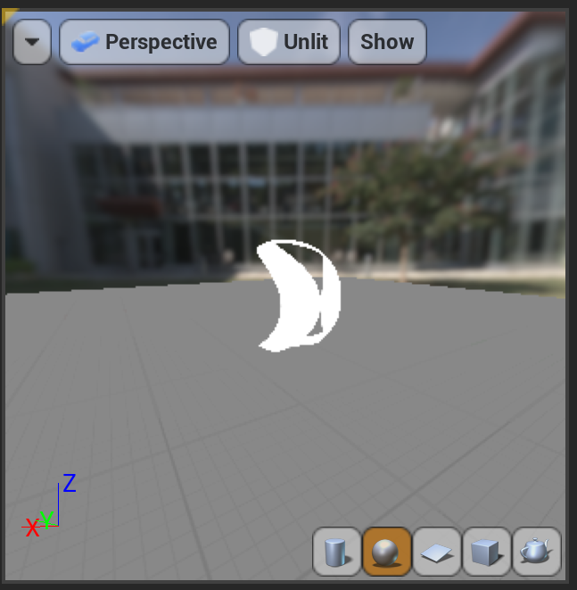

After Step 7, if you see your ring curved like this shape on the left, it is because you are viewing the (u,v) coordinates of the material wrapped around a sphere.
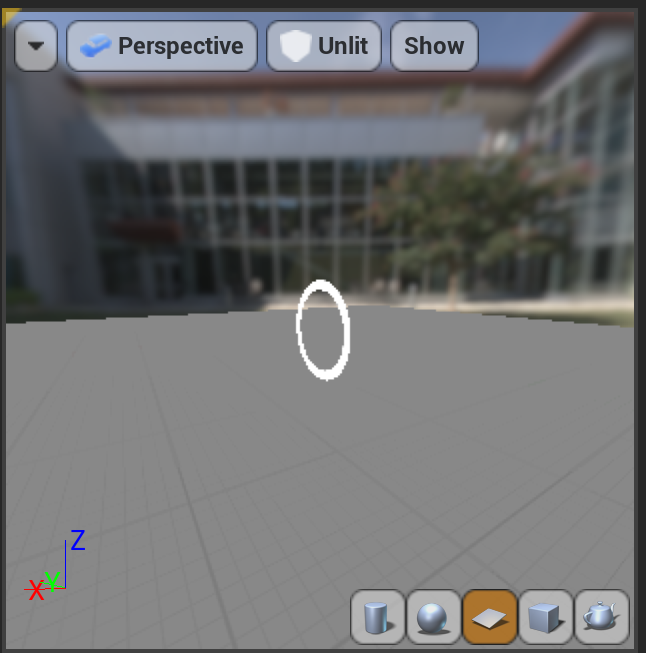
Change the projection setting at the bottom of the view from the sphere (in orange, left), to the flat plane (in orange, right).

With all of this in place, you should have a material blueprint that looks like the image below.

Apply it to a new component
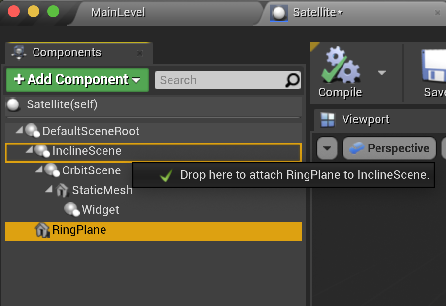

With our material created, we need to now add an extra component to our Satellite class to see it!
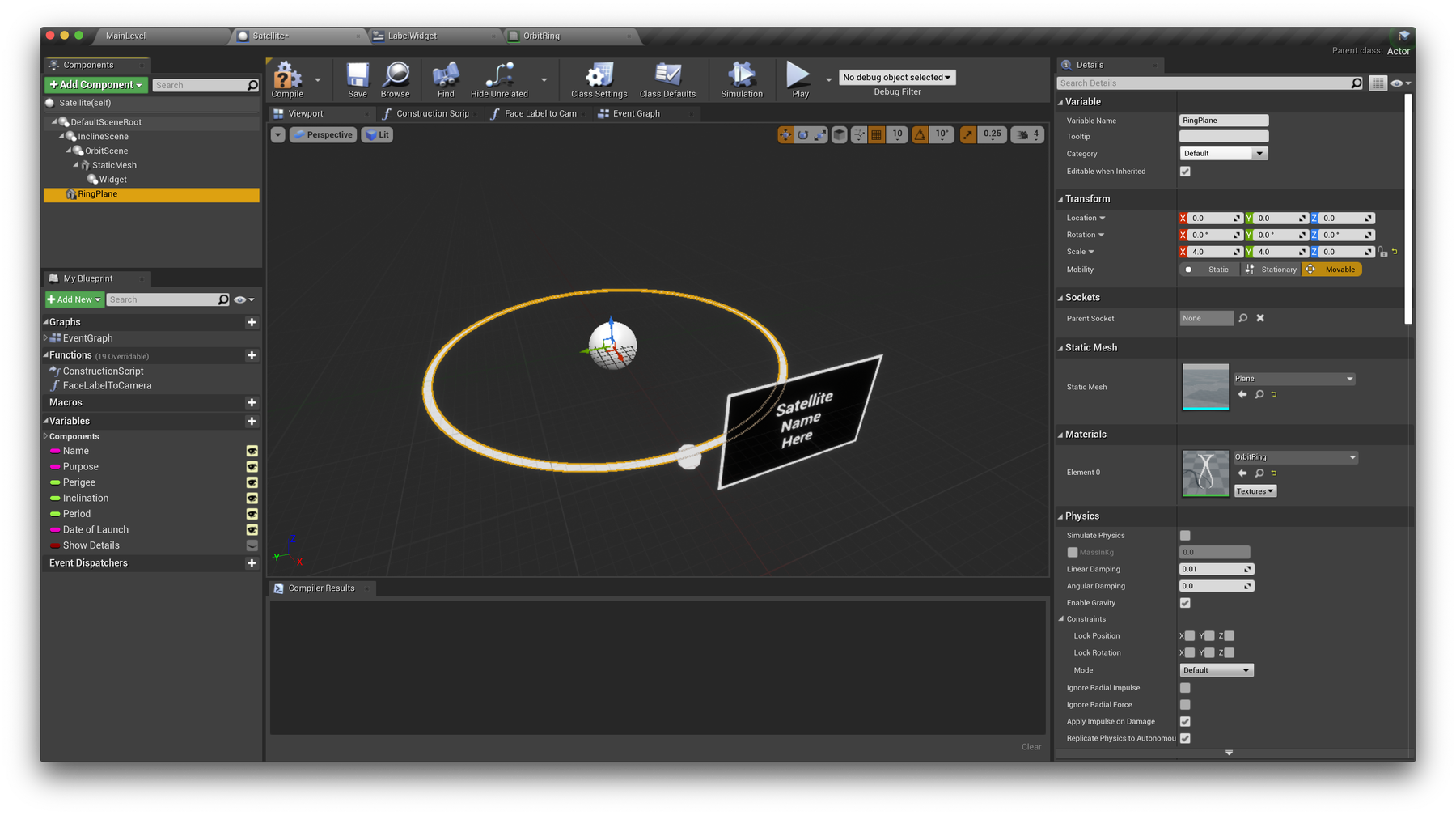
Return to your Satellite class, and +Add Component → StaticMesh, and name it RingPlane.
In the components tree, drag it to your InclineScene component to attach it. Now this plane will tilt with the inclination of the orbit.
With RingPlane selected, in the right Details panel, set the Static Mesh option to Plane which comes default in Unreal Engine (path should be /Engine/BasicShapes).
Set the Material option to your newly created OrbitRing material. Aha!
Scroll down to Collision and set Collision Presets to NoCollision. Experiment with the X and Y scale options to resize your ring, but don't worry about these values as we'll set them at runtime. You should hopefully see your material in action!
If you cannot find the Plane Object, you can get a new one.
Go to the Main Level, dive into the Satellite Folder, find the Basic->Plane actor in the list on the left. Drag it into the Satellite Content Browser.
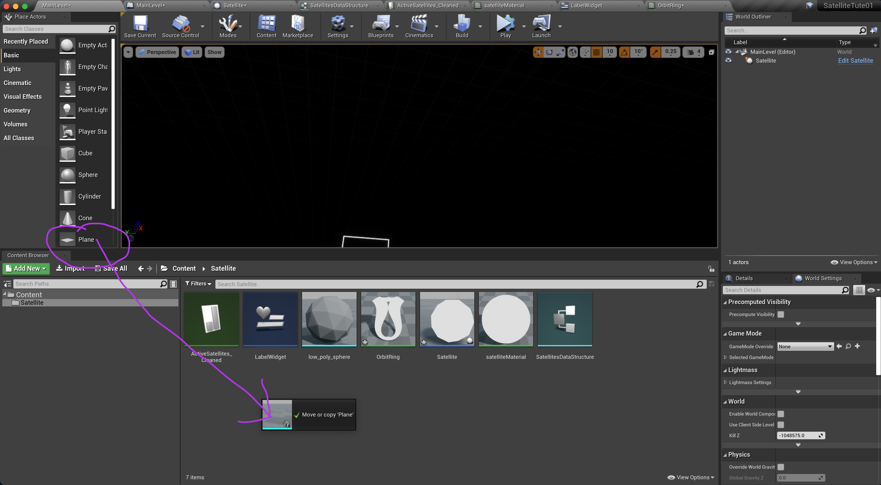

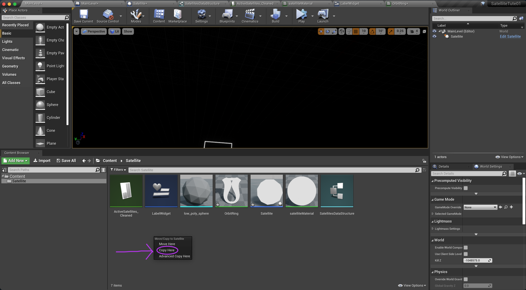
When dropped you're asked to Copy or Move?
Choose Copy.

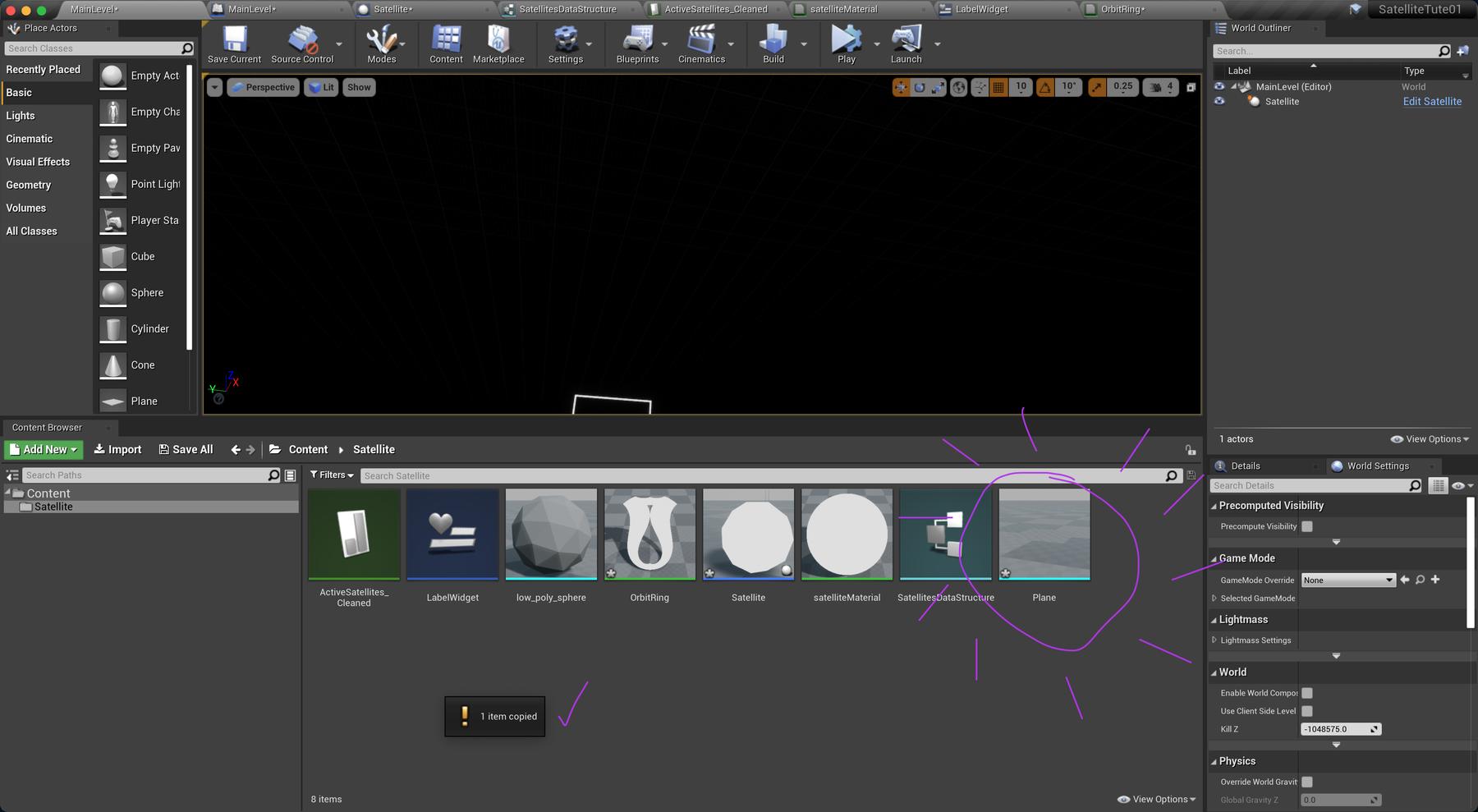
The new Plane Actor object appears in the Content Browser in the Satellite Folder, ready for use & references.
The rings we are about to add will be projected onto copies of this plane.

Now the new Plane object has been added to the Satellite Folder, return to the RingPlane Component, back in the Satellite Pane.
This time, on the right in the Details View click on the Static Mesh Menu.
You should see the Static Mesh menu includes the Plane we just added. Select it (see right).
Select the Plane
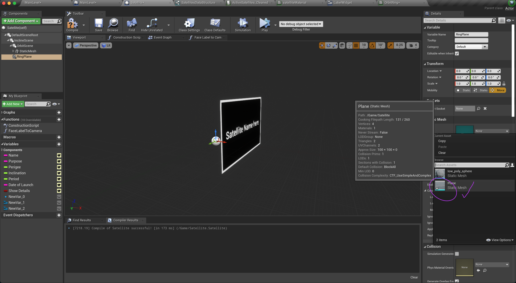

After selection, hover the mouse over the menu. It should indicate the path in a pop-up: /Game/Satellite/Plane
Set the Material option to your newly created OrbitRing material. It's there in the menu.
Scroll down to Collision and set Collision Presets to NoCollision. Experiment with the X and Y scale options to resize your ring, but don't worry about these values as we'll set them at runtime. You should hopefully see your material in action!

Resize at runtime
If you were to run your project now, you'll likely see a lot of small rings in the centre of the scene. Close, but not quite. We now need to set the X and Y scale of our RingPlane component to resize these rings and match our sphere's distance from the centre. Jump back into your blueprint after you've set the label text, and add the following.
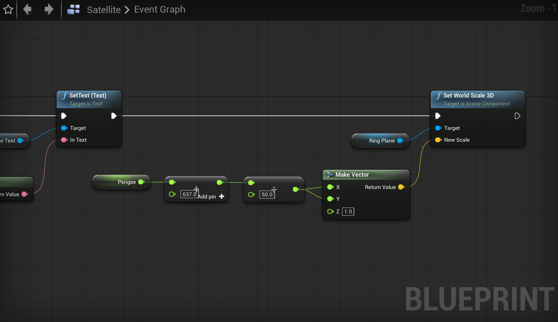

To break this down, we're going to run Set World Scale 3D on our RingPlane component. The scale input is in vector format for X, Y and Z. In our case, we just want to adjust X and Y, and leave Z at 1 (flat plane). Similar to setting the distance of our sphere, we'll use the Perigee data plus 637 for the earth's radius. As we're working in scale, we need to adjust this final value by dividing by 50 to line it up with our sphere.
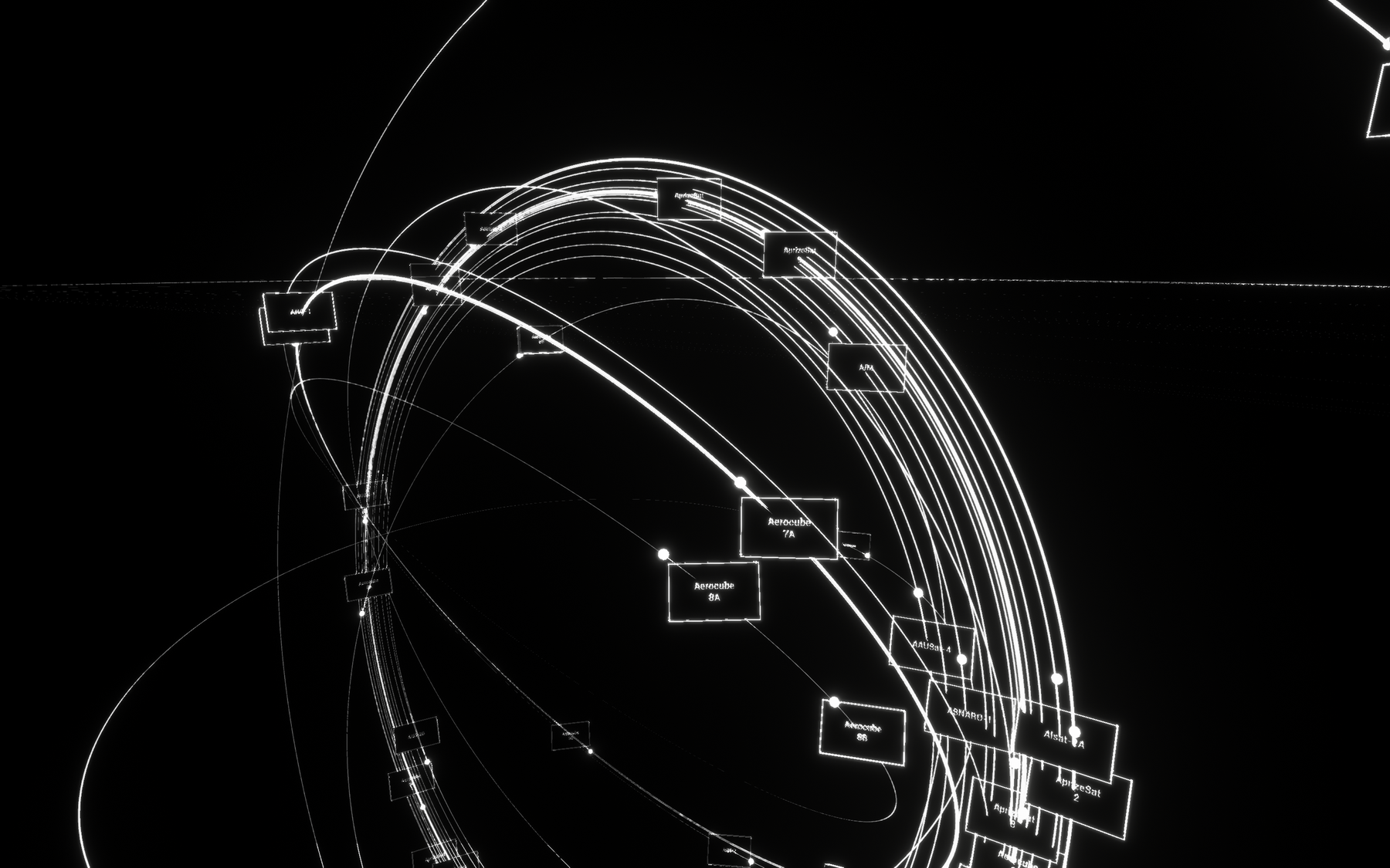
Great! Once you're done, you should see some pretty fantastic looking rings. Note: you might notice some scratchy aliasing artifacts on distant lines. This is due to a number of performance considerations in the editor but is unlikely to be present when packaged.



🎛 Toggle detail visibility
With these pieces in play, we've now created a fairly insightful simulation of satellites in orbit around earth. Well done! Before continuing, we'll add one more part to our Event Tick chain to make sure we only show our labels and rings when requested.
After calling your FaceLabelToCamera function, add a Branch node and pass in Show Details. Drag in references to you Widget and RingPlane components. Using Set Visibility nodes from the Branch, enable or disable visibility of these components (notice the checkboxes).
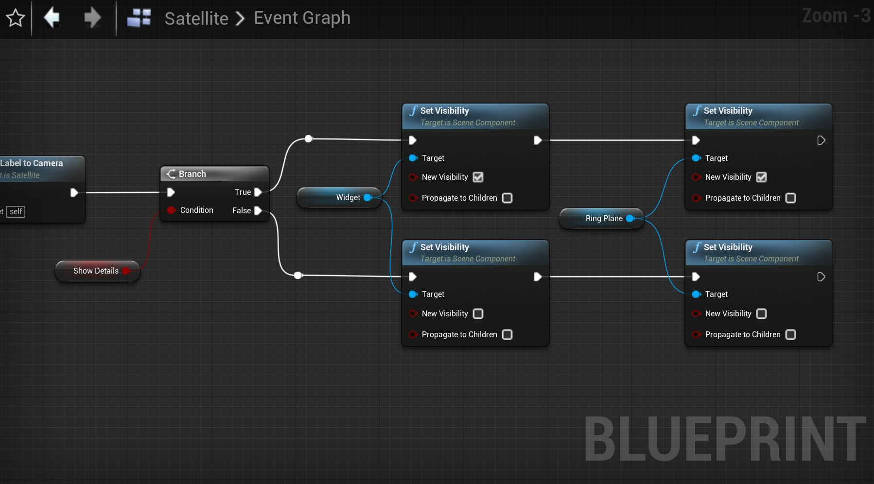

Now toggling the default value of the Show Details boolean will show or hide labels and orbit rings. Leave this set to true for now.
Read on to learn how we might integrate other data properties to highlight some of these objects.