Create a Satellite Class
To visualise our satellites, we're going to create a single Satellite class that can be "instanced" for each row in our spreadsheet. This class will let us set some common details between our objects, but also allow us to input unique data into each so they rotate and display differently.
Let's dive right in. Create a Satellite folder in your project content browser. In here, select Add New → Blueprint Class and select Actor. Give it a simple name of Satellite and open this asset. Let's first set up some variables so we can transfer our row data into each Satellite object.
Repeat with each property and type specified in your SatelliteDataStructure. Read more about creating Blueprint Classes here.
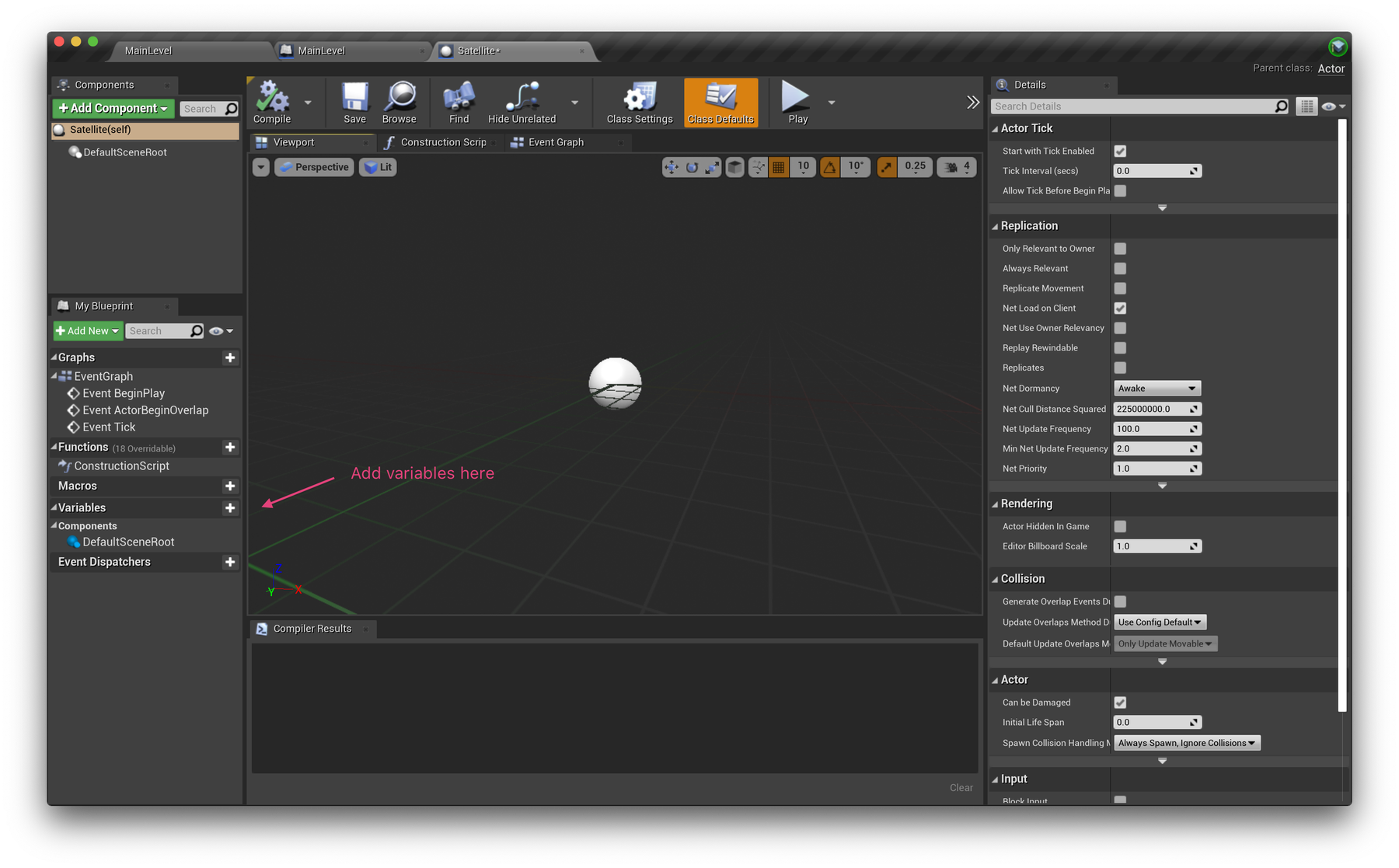

✏️ Variables set up
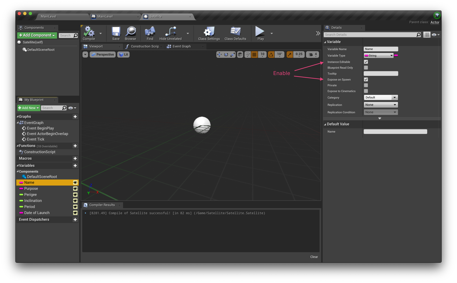
In the bottom left of the interface, select the + button next to Variables. We're going to create a variable for each column/property in our Data Table. You don't need to be strict on names here, so feel free to use "Name" instead of "Official Name of Satellite" for example.
Here's the steps for the first variable.
- change the Variable Name from NewVar_0 to: Name
- change it to type String
- check on: Instance Editable and
- check on: Expose on Spawn (enabled)
Do this for each variable, taking care to set the right sort of Variable Type (String or Float, etc). This will let us assign the values of these variables when we create new Satellite objects.
⌨️ Shortcut
Once you have made your first variable, if you RMB on the variable name in the LHS Column, you'll see an option to duplicate the variable. The keyboard shortcut is Ctrl+W. Doing this for variables of the same type means you only need to change the variable name.

✨ Create new objects at runtime
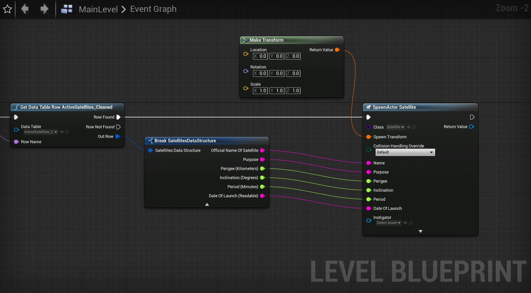
With our variables prepared, let's try creating Satellite objects from our Data Table. Head back to the Level Blueprint and the Get Data Table Row where we left off. Connect the Row Found output to a new Spawn Actor From Class node and select your Satellite class. You should now see input pins for our variables. These are here because we enabled the Expose on Spawn option. Go ahead and wire these up from your Break SatelliteDataStructure node like below.
Note: the Spawn Actor From Class node requires a value for the Spawn Transform input. This basically specifies where in your world the actor will be placed. Add a Make Transform node to your graph and connect it here. We'll have our satellites rotating from the centre of the scene (x:0, y: 0, z: 0), so leave the default settings.

⚙️ Component setup
Next, let's set up our Satellite actor's components. A component is simply a part of what makes up an actor. Components can be static mesh shapes, lights, sounds, 3D widgets etc. Read more about components here.
Create a scene!
Head back to your Satellite class and find the +Add Component button (top left) and explore the Menu's options. There's a lot!
Our Satellite class will be quite simple, so we don't need many components, however working with multiple rotations can be tricky, so we'll utilise Scene components to help us break them into a sequence of steps.
A Scene component is a dummy wrapper — it's simply a way to group components, in preparation for some transformation. It's used to transform everything inside it (location, rotation and scale). There can be scenes inside scenes (which in turn get additional transforms).
They're sometimes called parent/child transforms, or a transform heirachy.
Let's assume the Earth is set to be at the World Origin (0,0,0). We can place it later. For now, we'll create two Scene components to help manage the rotation of our satellites around this centre-point. A video below will help demonstrate this.
Start by adding two Scene components, and a Static Mesh component, and name them as you see below.
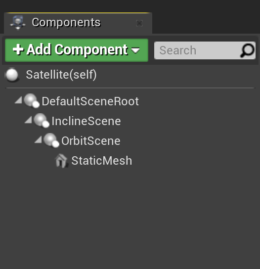

The DefaultSceneRoot should already be there.
The InclineScene will be rotated on its X axis to simulate the orbital tilt (compared to the equator) of the satellite. This will be set by the Inclination data column.
The OrbitScene will be rotated on its Z axis to simulate the position of the Satellite along its orbital path around the earth. This will be set by the Period data column and adjusted over time.
The StaticMesh component will let us display a visible sphere/ball object to visually represent the satellite.
Notice the items in the list (above) are indented? They're not at the same indentation level. Check your list. They're like folders inside folders - this indicates the transform sequence order. Incline rotation, then Orbit (period) rotation. If they are at the same level, or do not cascade as above, you can drag&drop items in the list.
⚽️ Add a Static Mesh
Our StaticMesh component needs a StaticMesh object assigned to it for us to actually see anything. Unreal Engine comes with a few basic shapes including a sphere which you might like to use. We're generating over 1400 copies of this actor. For better computer display performance it might be wise to use a less detailed shape.
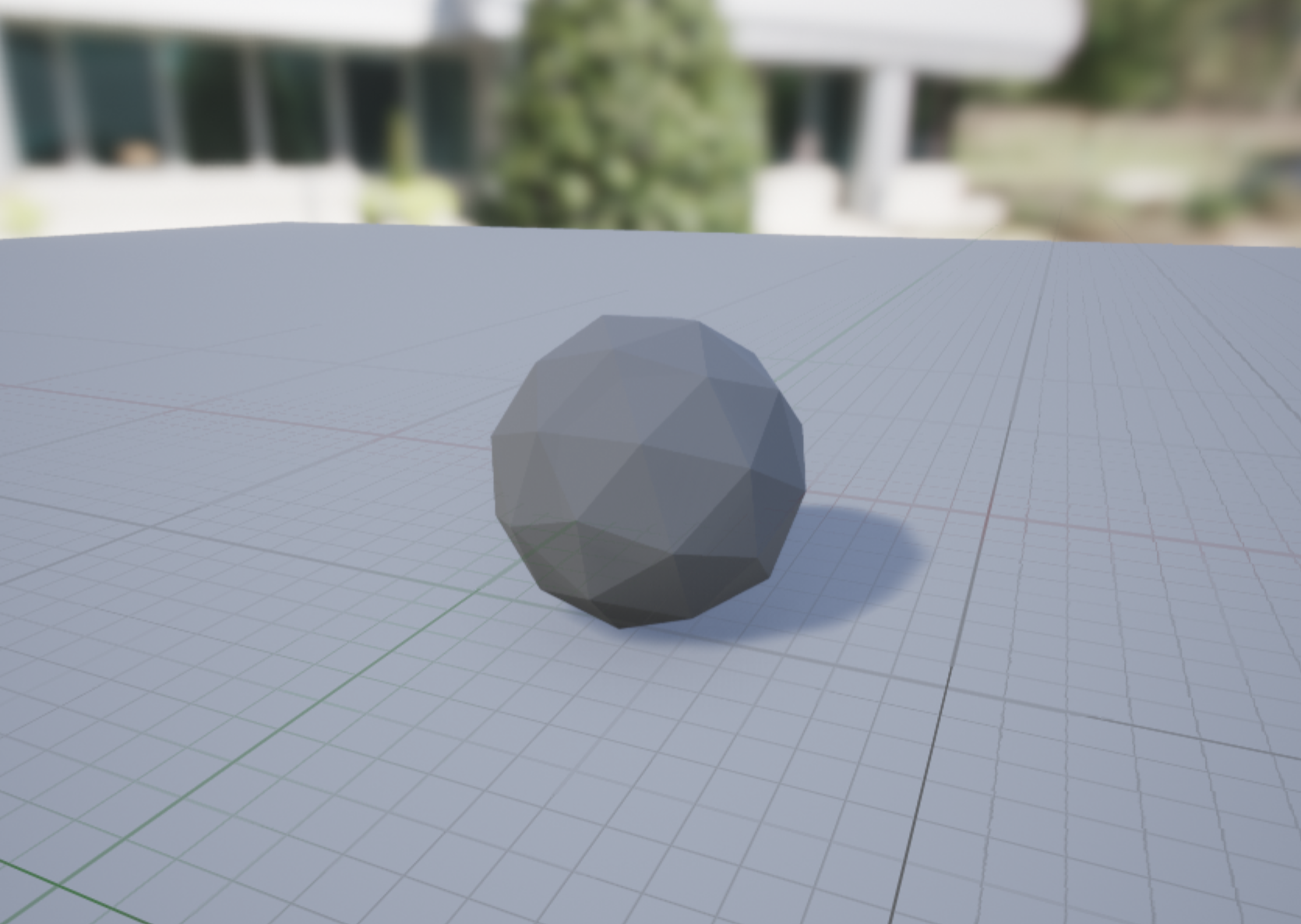

Preview of the low_poly_shere asset.
We've created a "low poly" (low polygon count) sphere in Houdini which you might like to use instead. If so, download and import the following file into your project with Import Uniform Scale set to 100 as this file was created in units of metres and UE operates in centimetres.
Click on the Import Button (right) in the Content Browser Window. Select the Low Poly Sphere FBX file you downloaded (above).
A new asset icon will appear in the Content Browser. There should be five there now.
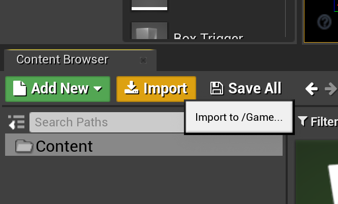

Select the Satellite Asset again - double-click the icon in the Content Browser. Or change to the Satellite Pane, if you have it tabbed.
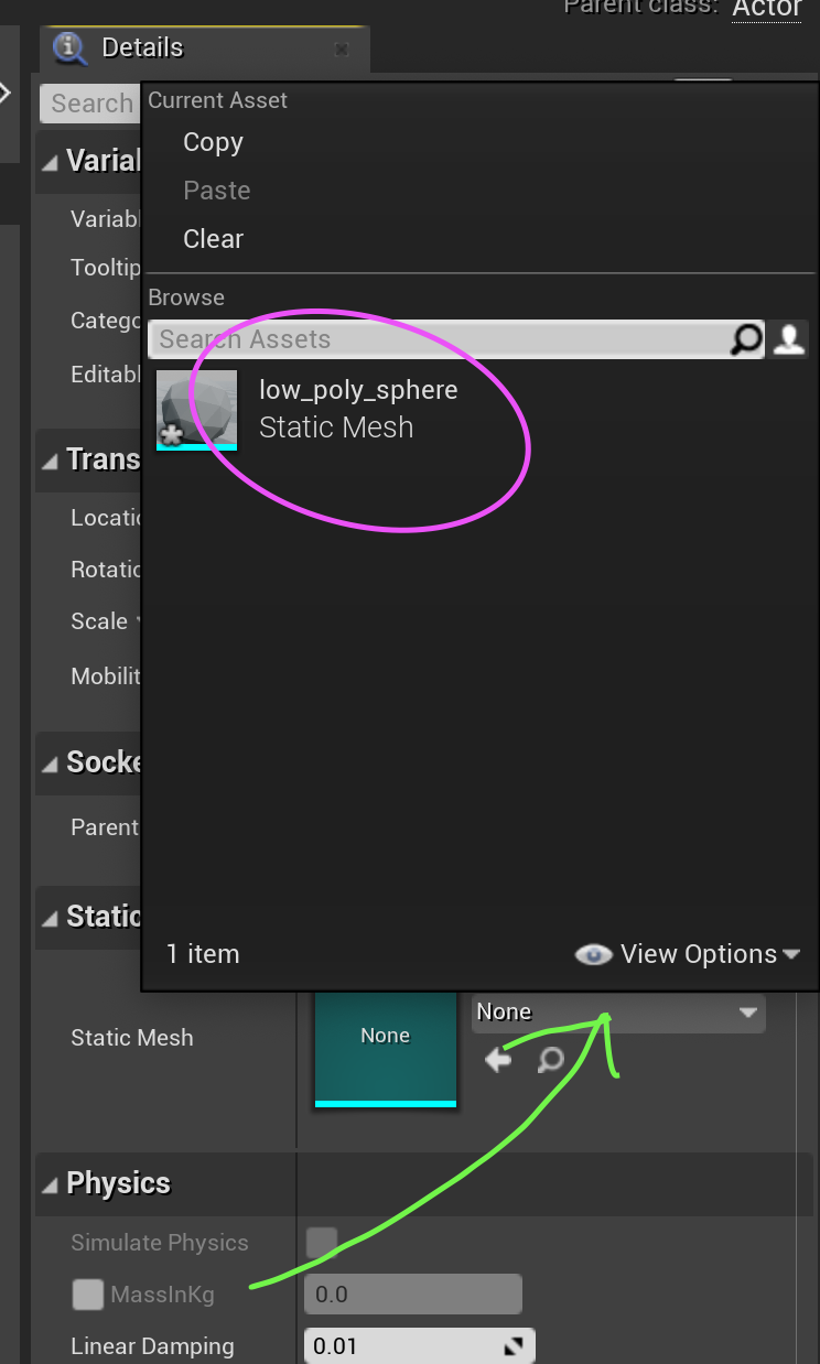
In the Details pane on the right-hand side of the screen locate the Static Mesh section, and click on the Menu item which says "none" - (see green arrow right).
A list should appear (right). Select "low_poly_sphere" Static Mesh (circled pink).
If you imported some other shape, it should appear in this list.
After this, adjust the Scale of this component to roughly 0.2. You'll likely adjust this later.

Review
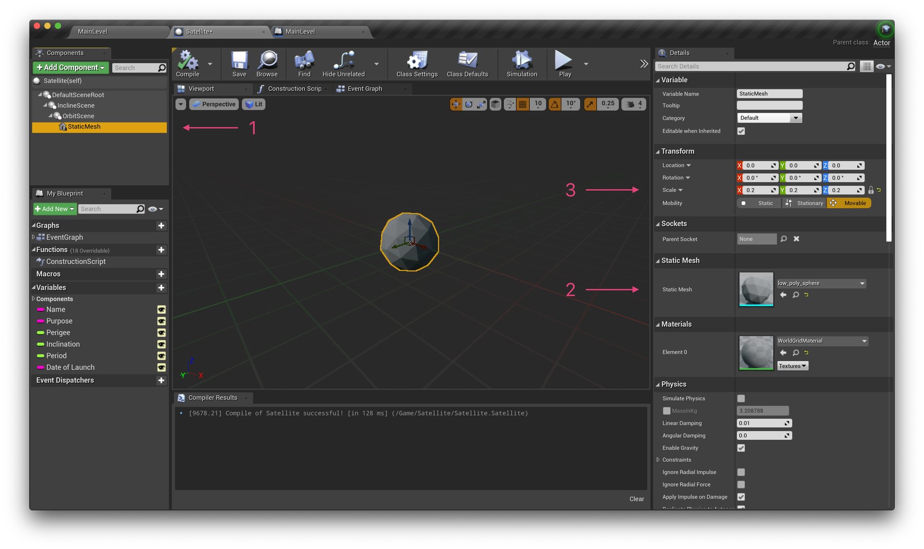
(see numbers in the image below)
- We selected the Static Mesh Component for modification
- We selected a Static Mesh Object
- We changed the Scale from 1.0 to 0.2

🧪 Experiment with rotations
As explained above, our two Scene components will assist us with rotating our satellites around the world centre (earth). The video below will help demonstrate how this will work when we run our project. Firstly, we'll set the X position of our StaticMesh sphere relative to its real distance from Earth. We'll then set to Y axis rotation of our InclineScene according to the inclination of the satellite, and update the Z axis rotation of the OrbitScene to create an orbiting animation. This will all be set in our Satellite's blueprint next.
Feel free to experiment with these adjustments, and don't worry about where you leave these settings as they will be overwritten when our game is played.
🎨 Create a SatelliteMaterial
Before we go much further, let's quickly create a bright, white material to assign to our sphere so we can see it in our dark scene. Select Add New → Material in your Satellite folder in the Content Browser and name it SatelliteMaterial. If you're new to materials in Unreal Engine, have a look at this page.
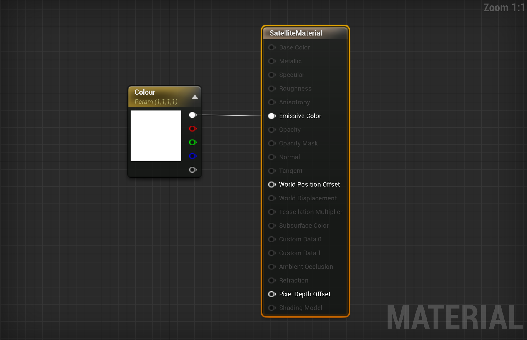
Once opened, switch the Shading Model in the left Details sidebar to Unlit. Add a Constant3Vector node to your graph, change the colour to white and connect it to the Emissive Color pin. To allow us to modify this colour value per object later in this tutorial, right-click on your colour vector node, choose Convert to Parameter and label it "Colour".
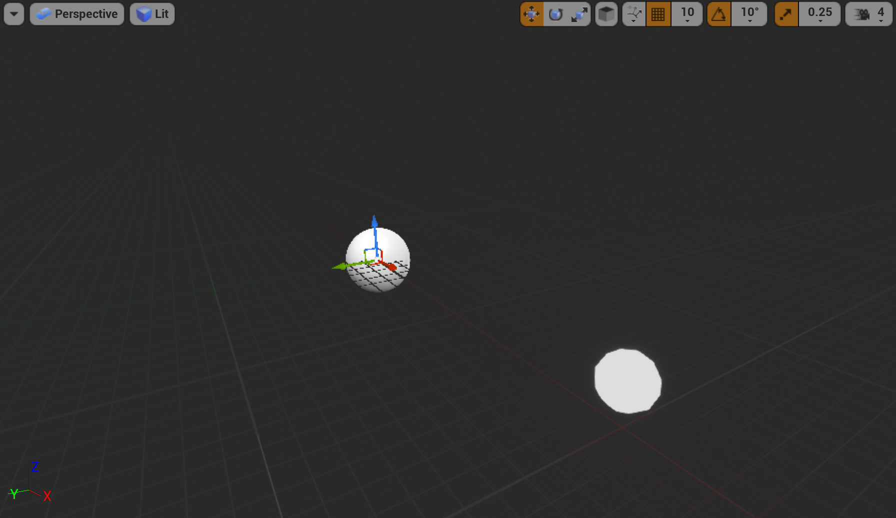
To finish up, head back to your StaticMesh component and set its material to your newly created SatelliteMaterial and hopefully it should update to white in your viewport!


💫 Position Satellites from the data
Let's dive into our Satellite's blueprint to build our visualisation. At the moment, your Event Graph should be mostly empty except for event nodes for BeginPlay and Tick. Here's what we'll tackle next:
- Rotating our InclineScene component according to the Inclination data
- Rotating our OrbitScene component for an initial random distribution
- Positioning our sphere according to the Perigee data (closest distance to earth)
- Rotating our OrbitScene over time according to the orbit Period data
Set the incline angle
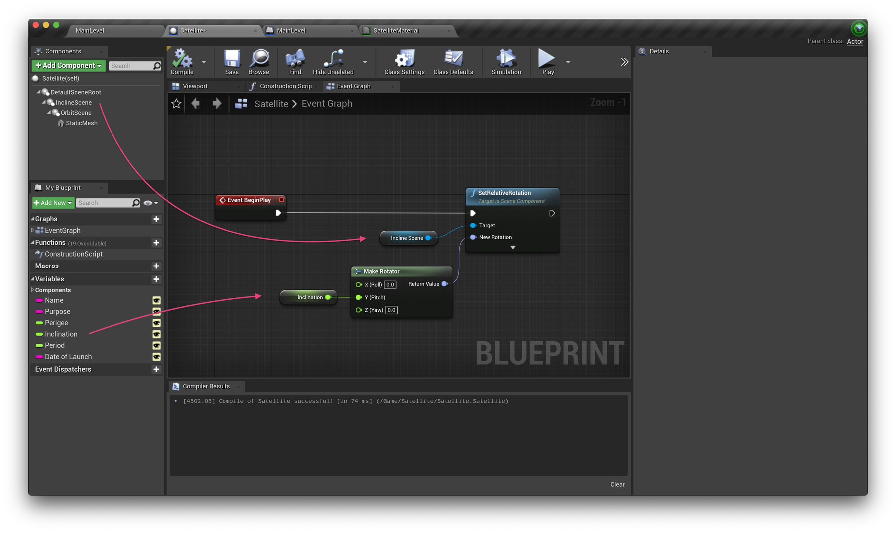
Bring in references to the InclineScene component, and your Inclination variables from the left of the interface (click and drag, and choose Get). Add a SetRelativeRotation node and a Make Rotator node and wire these up like below. Thankfully, our incline data is already in degrees so nothing further is required.

Set an initial orbit distribution
To move each satellite along its orbit, we'll set the Z axis rotation of the OrbitScene. Soon we will increase this value on the Event Tick over time, but to initially distribute the satellites along their paths, we can set a random rotation value.
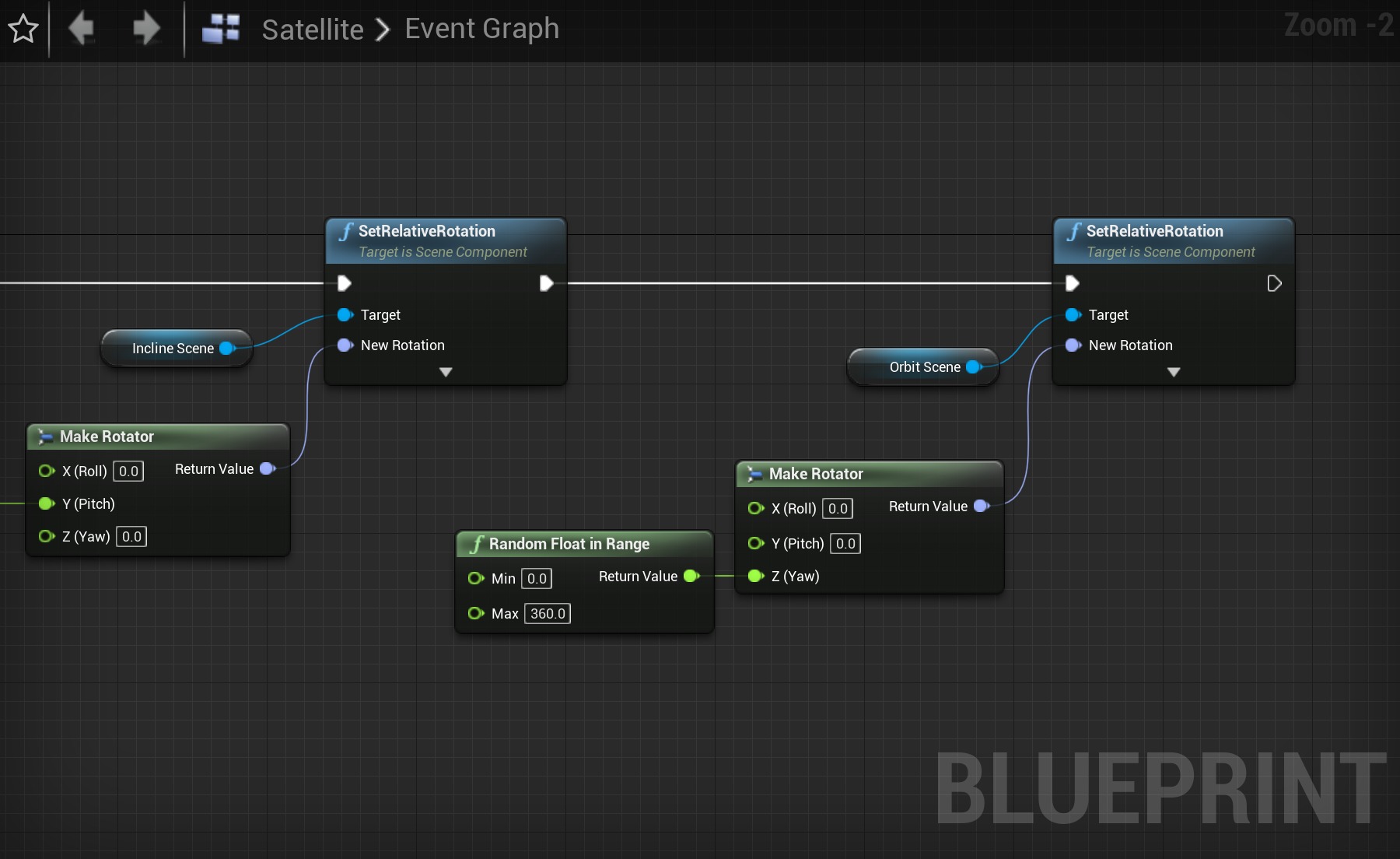
Similar to the above, drag a reference to the OrbitScene into the graph, and connect it to another SetRelativeRotation node. For the rotation value, add another Make Rotator and wire up a Random Float in Range (0–360) node to the Z (Yaw) input, like below.

Set the distance from earth
With our initial rotations taken care of, we now need to push our StaticMesh component sphere away from the origin of the scene/world (where our earth will be). To do this, we'll need to drag in a reference to our StaticMesh component, and the Perigee variable. Use a SetRelativeLocation node to push the sphere outwards on the X axis. The value will be an addition (using a float + float node) of the Perigee value, and 637 representing the earth's 6,378 km radius at our 1:1000m scale (remember Unreal Engine operates in centimetres.)
Your Satellite Event Graph should now be looking something like the screenshots below.
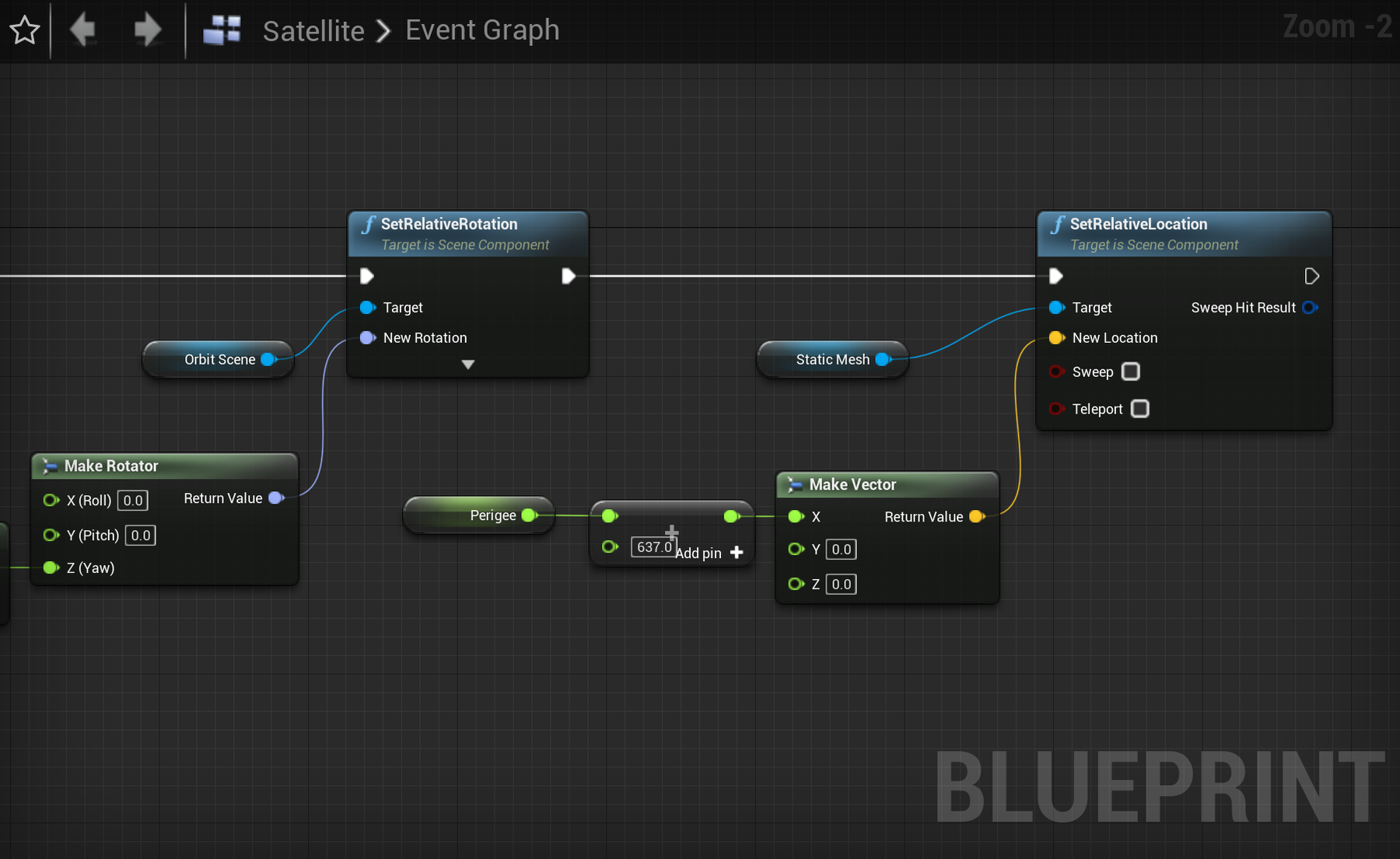

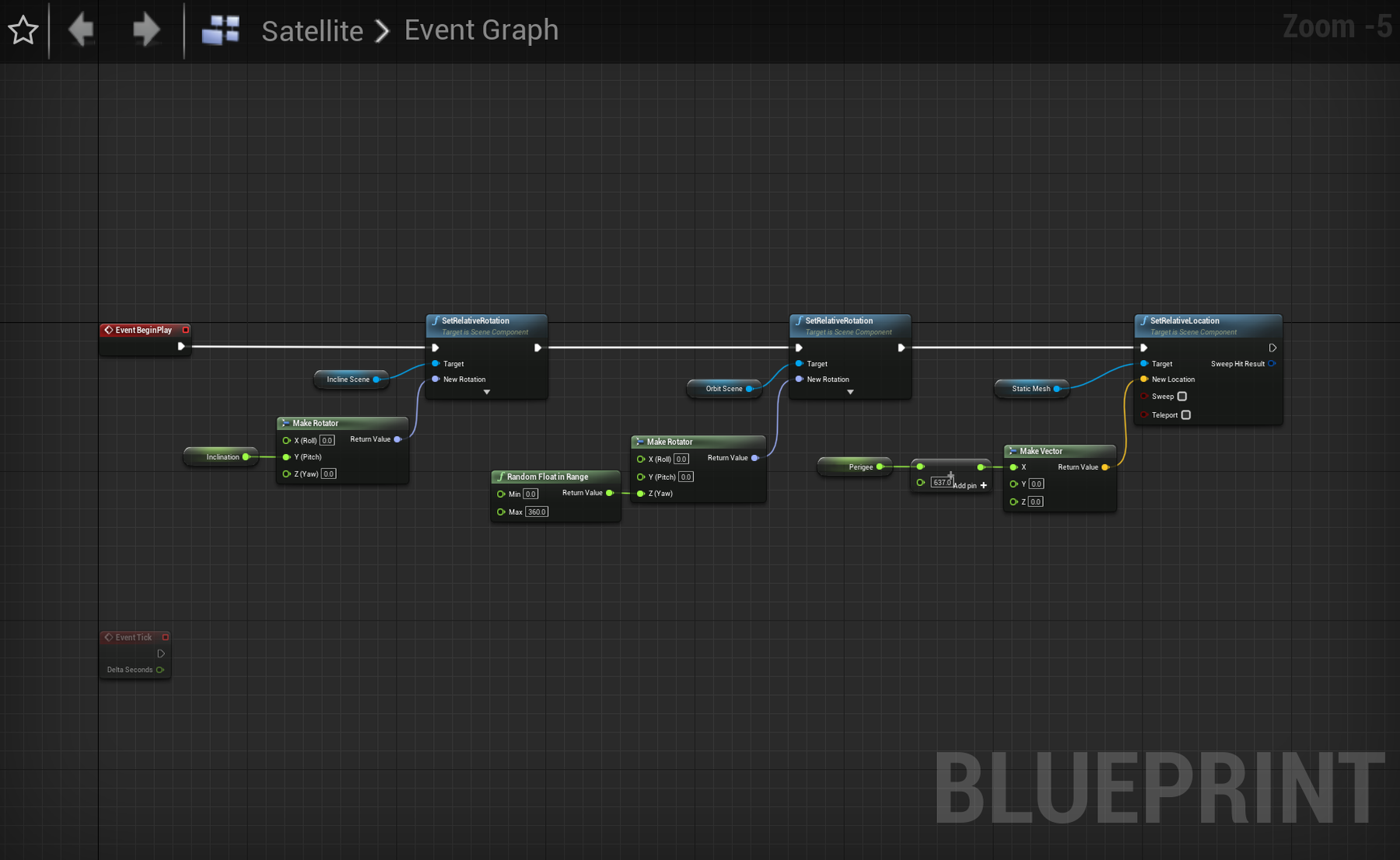

The entire BeginPlay chain so far.
Run your project!
Head back to your main level window and hit play to run your project. You should now be seeing your Satellite objects projected outwards from the centre of your scene, with clear patterns of common inclines and distances from earth starting to show. At the moment the centre of our scene is just empty space but we'll create an Earth actor later in the tutorial. Here's a video of our project so far, navigated by the mouse and WASD keys.
💫 Rotate Satellites along their orbit
It's time to take our Satellite objects for a spin. Using the Period data, which is in minutes, we can create a scaled simulation of how these objects actually travel over time.
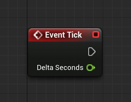

Firstly, take a look at the Event Tick node. If you haven't used it before, this node runs constantly, once per frame, as our game is played. The Delta Seconds output provides the number of seconds that have occurred between frames.
At an ideal frame rate of 60fps, this number will sit at around 0.016. If our program slows down, this number will increase. This will allow us to make sure our Satellite objects are moving true to time regardless of runtime frame rate (which will always fluctuate).
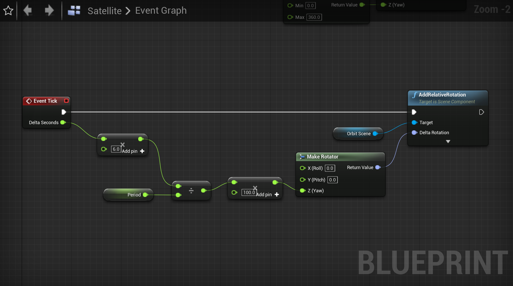
To get started, drag in references to your Period variable, and the OrbitScene component. As our Period data is in minutes, let's start by ensuring our satellites will all rotate 360º after 1 minute, then we can multiply this by Period to adjust this scale per object.
To do this, first multiply Delta Seconds by 6, so after 60 seconds the cumulative result will be 360. Then divide this result by your Period value, assign it to the Z axis of a rotator and add this rotation value to the OrbitScene component like below.
Run your project and take a look! See anything moving? You might have to fly right up to a satellite point to notice any motion as we're in real time. Return to your blueprint, and multiply the final value by 100 to speed things up (or any value you like).

👍 Wrap up
Well done! You've now created a working simulation of satellites in orbit around earth. It's worth noting at this point that we've only used the perigee property of our dataset. Not all satellites have a perfectly circular orbit—in fact very few do—however we're pretending they do here. You might want to expand your program to incorporate the apogee property as well, to either calculate an average of the two, or design an accurate elliptical orbit that demonstrates the eccentricity of each orbit path.
Continue reading to add informative labels and rings to your satellites.